3
J5
F1
J4
LD1
P2
LD3
J8
F2
DS1
P1
LD2
J1
J7
J3
J10
These instructions apply to control unit:
531R
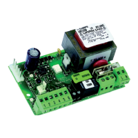
The 531R control unit (Fig. 1), installed on 531R and 531K operators,
has an integrated receiver (433 MHz) to command, by remote
control, the opening and closing of the automated system, and
does not require any outside radio receivers.
Fig. 1
1. 531R CONTROL BOARD
egatlovylppusrewoP
zH05-)%01-%6+(.caV032
seirosseccarofylppusrewoP
.cdV42
seirosseccarofdaolxaM
.Am002
erutarepmetgnitarepO
C°55+C°02-
sesuF
)1elbaT(,2F,1F
scigolnoitcnuF
citamotuaimeS/citamotuA
stupnidraoblanimreT
EFAS-LIAF/SECIVEDYTEFAS/POTS/NEPO
remitthgilysetruoC
.nim2
smetsysycneuqerfoidaR
edocgnippohhtiwzMH334
1F
)noitcetorprotom(.V052/.A01dipar02x5esuF
2F
)seirossecca(esufelbarotseR
1J
seirossecca/stupnirofdraoblanimretegatlovwoL
3J
tupnirewopcaV032rofdraoblanimreT
4J
gnidniwyramirpremrofsnartrofrotcennoC
5J
rotcennocthgilysetruoC
7J
gnidniwyradnocesremrofsnartrofrotcennoC
8J
rotcennoctuptuorotoM
01J
annetnalanretxerofrotcennoC
1P
nottub-hsupNEPO
2P
nottub-hsupPU-TES
1SD
sehctiws-pidgnimmargorP
1DL
DELsutatstupniNEPO
2DL
DELsutatstupniPOTS
3DL
DELsutatstupniWSF
1.1. TECHNICAL SPECIFICATIONS
1.2. PARTS OF 531R BOARD (Table 1)
1.3. DESCRIPTION
1.3.1. Terminal boards and connectors
TERMINAL BOARD J1 (low voltage)
OPEN= Open command (N.O.)
Any device (push-button, etc.) which, by closing a contact,
supplies an opening (or closing) pulse to the door.
To install several Open devices, connect N.O. contacts in parallel.
STOP= Stop command (N.C.)
Any device (e.g. a push-button) which, by opening a contact,
stops movement of the door.
To install several stop devices, connect the N.C. contacts in series.
N.B.: if stop devices are not used, jumper connect STOP
to the inputs common contact.
= Inputs common contact/accessories supply negative
pole.
= Accessories supply positive pole (24Vdc 200mA max)
FSW = Closing safety-devices contact (N.C.)
Safety devices are all devices (photocells, sensitive edges,…) with
N.C. contact, which, if there is an obstacle in the area they protect,
operate to reverse door closing movement.
If the safety devices are activated when the door is locked or
open, they prevent it from closing.
To install several safety devices, connect the N.C. contacts in
series.
N.B.: if no safety devices are connected, jumper
connect FSW to the -TX FSW terminal
-TX FSW= Terminal for connection of the negative pole (-) of the
photocells transmitter (TX).
J3 TERMINAL BOARD (high voltage)
Terminal board for connecting 230Vac 50Hz power supply.
J10 TERMINAL BOARD (external antenna)
A terminal board for connecting an external antenna (Optional
item) instead of the supplied standard conductor.
terminal for connecting the shielding of any external antenna.
1.3.2. Programming dip-switches (DS1)
Failsafe
If activated, it enables the photocell operating test before every
movement.
Anti-crushing sensitivity
For doors with an irregular movement, it reduces the sensitivity of
the anti-crushing device to prevent unwanted action by it.
Radio codes programming
If activated, it enables the 531R board to save the radio codes
of the remote controls. (see chapter 4.1).
Speed adjustment
If door movement is too quick or irregular, you can select low
carriage speed.
531R CONTROL UNIT
.oNnoitcnuFFFONO
1efasliaF
evitcAevitcanI
2ytivitisnesgnihsurc-itnA
woLhgiH
3gnimmargorpsedocoidaR
evitcanIevitcA
4deepsegairraC
hgiHwoL