CONTROL UNIT 596/615 BPR
On boards supplied as a spare part or with operators on
which the limit-switches are optional items, the contacts of
connectors J6 and J9 are short circuited. If sensors are being
installed, eliminate the jumpers and connect the limit-switches
directly or via the specific adaptor, to the connectors. When the
travel-limit sensor is engaged, operation varies according to ope-
ration setting as 596 or 615 (J3).
596
Opening: immediate stop when sensor is engaged.
Closing: when the sensor is engaged, the operator works for 4 sec in
slow-down and for 1 sec. at standard speed (over-pushing stroke).
615
Opening and closing: when the sensor is engaged, slow-down is
executed with a duration of half the time at standard speed.
If the travel-limit sensors are not installed, the appliance executes
only the learnt work time (see par.6.2).
1. WARNINGS
Before attempting any work on the electronic equipment
(connections, maintenance), always turn off power.
- Install, upstream of the system, a differential thermal breaker
with adequate tripping threshold.
- Always separate power cables from control and safety cables
(push-button, receiver, photocells, etc.). To avoid any electrical
disturbance, use separate sheaths or a screened cable (with
the screen earthed).
Terminal Description Device connected
1
OPEN
Device with N.O. contact
(see chap. FUNCTION LOGICS)
2
CLOSE
Device with N.O. contact
(see chap. FUNCTION LOGICS)
3
STOP
Device with N.C. contact which cau-
ses the automated system to lock
4
- 24Vdc
Power supply for accessories
5
+ 24Vdc
6
SAFE
Closure safety device with N.C.
contact
(see chap. FUNCTION LOGICS)
7
OP
Motor opening stage
8
COM
Motor common contact
9
CL
Motor closure stage
10
LAMP
Output for flashing light
230 Vac max 60W
11
COURT.
Output for courtesy light 230
Vac max 40W
timing 90 sec. not modifiable
12
COM
Common contact for light/flashing light
13 - 14
L - N
Board power supply (230Vac)
Description of terminal boards
An RP2 type 2-channel receiver can be connected to the
J2 connector, so that the OPEN and CLOSE facilities of the
automated system can be commanded directly with a 2-
channel radio control.
If using a single-channel RP type receiver, only OPEN can be com-
manded.
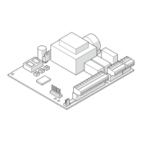
4. CONNECTIONS
Other Safety
Devices
BLUE
Fig. 2
Power supply voltage 230V~ - 50Hz
Absorbed power 4 W
Motor max. load 800 VA
Accessories max. current 250 mA
Enviroment temperature -20°C to +55°C
Fuses F1 = 6.3A-250V F2 = self-resetting
Operating logics B/C, B, C, EP, AP, P, A default = EP
Work time (time-out)
Self-learning (0-10 min in 2.5 sec steps)
Default = 10 min
Pause time
Self-learning (0-5 min in 1.5 sec steps)
Default = 15 sec
Terminal board inputs
Open, Close, Stop, Limit-switch,
CL safety devices, Power supply
Terminal board outputs
Motor, flashlight, courtesy light
and power supply to accessories
Programmable functions
Operation for barrier or up-and-over
Logic
Functions through learning Work time, Pause time
2. TECHNICAL SPECIFICATIONS
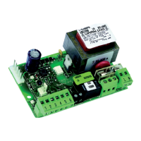
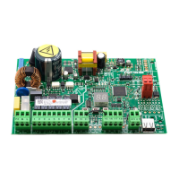
3. LAYOUT AND COMPONENTS
Description of components
J1 inputs terminal board and power supply to accessories
J2 connector for radio receiver (see Note)
J3 select operation: 596
or 615
J4 motor terminal board
JS 230 Vac power supply terminal board
J6 opening limit-switch connector (N.C. contact)
J7 OPEN command connector (for up-and-over)
J8 terminal-board for flashlight and courtesy light
J9 closing limit-switch connector (N.C. contact)
LED Signalling LEDs
SW1 programming key
TF1 transformer
F1 6.3A- 250 V (motor protection)
F2 self-resetting (accessories protection)