E045 32 732786 - Rev.C
VOLTAGE
USB
USB-A
2EASY
BUS MON.
RADIO2RADIO1
ERROR
HIGH
AREA
LAMP OP-ACOMAC MAIN W.L.24V
8
7
CL
M2
OP
M1
COM
BUS
212018171615
24V5V
96543
CL
2
OP
1LNPE
2EASY
LOCK
24V
J1
J2 J11
J9
J3
87
M2
M1
9654
321
LNPE
8.8.
RADIO 433-868
J5
PE N L
1 2 3 4 5 6 7 8
9 10 11
15 16 17 18
20 21
RL1 RL2 RL3 RL4 RL5
TH2 TH1
QC4 QC3
IC1
C52
TF1
F1
FL1
DB1
+
-
/R1
F
/R2
STOP
DL7DL8
DL9
DL14
DL15
DL16
DL11 DL12
DL10
DL17
DL13
SW3SW1 SW2
ENGLISH
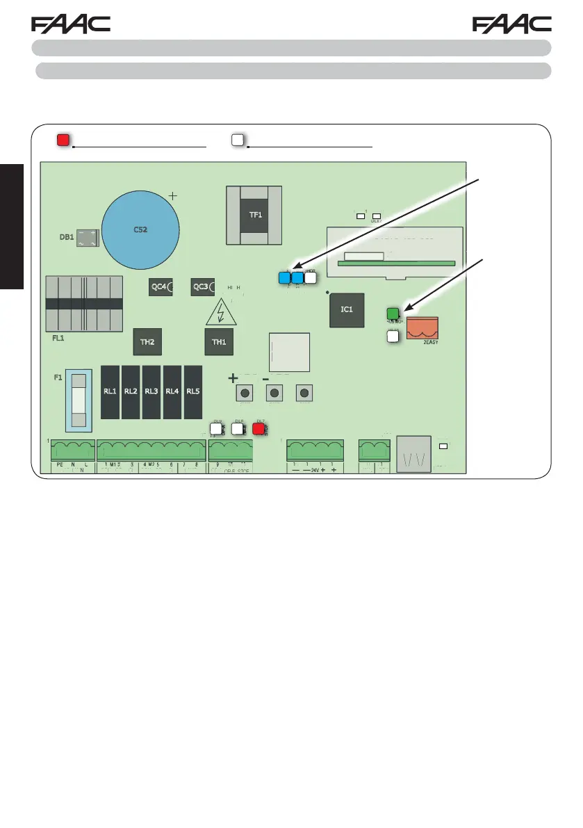
7. START-UP
7.1 CHECKING THE LEDs
After having made all the connections and powered the board, check the status of the LEDs in relation
to the status of the inputs (the Figure shows the condition of closed automated system).
For the meaning
of the LEDs,
see “BOARD
LAYOUT”
For the meaning
of the LEDs, see
“
BUS-2EASY
DEVICE ENTRY
PROCEDURE”
STOP - In default configuration, the STOP input is a safety input with contact N.C. (Normally Closed).
The corresponding LED must be ON with the automated system at rest and go off when the connected
device is activated.
OPEN A, OPEN B - In default configuration, the OPEN A, OPEN B inputs are inputs with contact N.O.
(Normally Open). The corresponding LEDs must be OFF when the automated system is at rest, and
go ON when the connected device is in use.
Led ERROR - FLASHING = there is an alarm in progress (situation that does not compromise gate
operation) - see “ALARMS”. ON STEADY = there is an error in progress (situation that blocks operation
until the cause of the fault has been eliminated). See “ERRORS”.
LED ON = contact closed LED OFF = contact open
 Loading...