3
4
E124 8 532365 - Rev.A
Ø16/20/25
Translation of the original instructions
ENGLISH
5. INSTALLATION
RISKS
PERSONAL PROTECTIVE EQUIPMENT
F
CARRY OUT THE WORK WITH THE ELECTRICAL POWER
SUPPLY DISCONNECTED.
If the power disconnect switch is not in view, place a
“WARNING - Maintenance in Progress” sign on it.
Turn the power on only after having made all the
electrical connections and carried out the preliminary
start-up checks.
Never remove the board cover unless the instructions
specifically indicate that you should do so.
!
Handle the enclosure carefully so as not to damage the
board and the components.
TOOLS REQUIRED
8 4
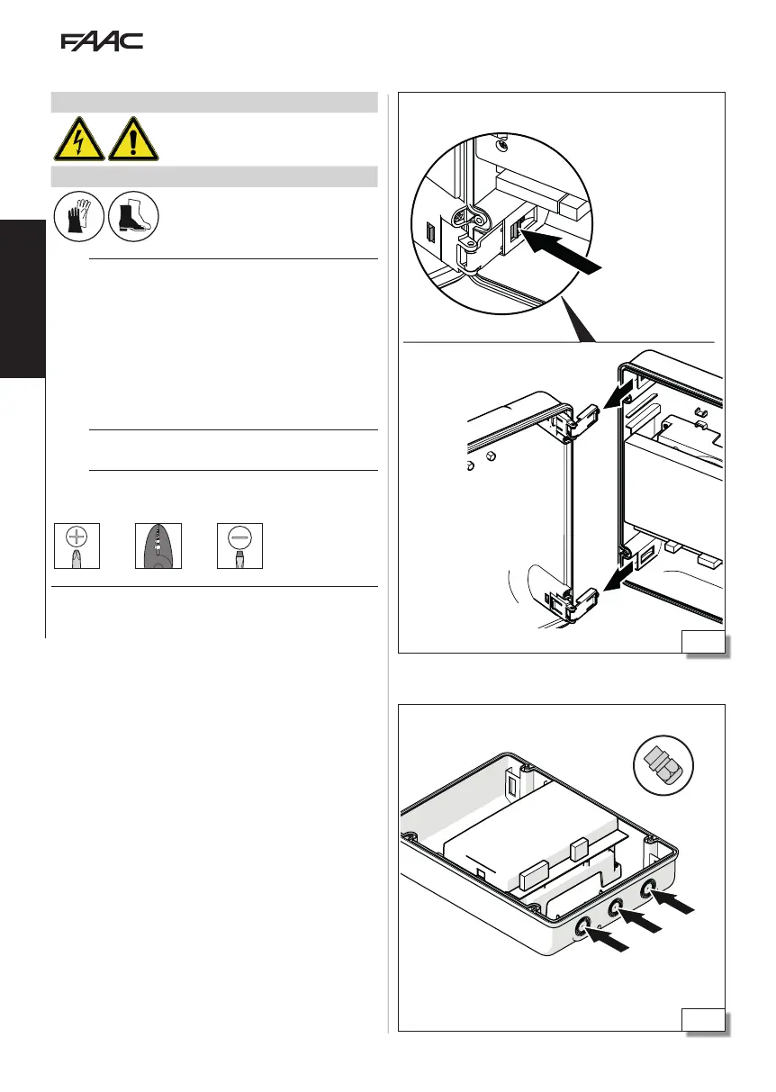
5.1 INSTALL THE ENCLOSURE
REMOVE THE COVER
(3) To release the hinges, press on the catch of each
hinge and then remove them.
PREPARE THE CABLE ROUTING HOLES
(4) Open the cable routing holes to a diameter
suitable for the diameter if the conduits. Install suit-
able cable glands.
Remove the cover
Prepare the cable routing holes
(open to a suitable diameter)
 Loading...