13. Position smoke alarm to mounting plate and turn clockwise to
lock into place. (To engage tamper resist feature, insert pin
into notch on edge of smoke alarm after smoke alarm is posi-
tioned properly in base. Refer to step #10 on previous page.)
NOTE: Smoke alarm will not mount to plate if battery is not installed.
14. Turn on power at main fuse box or circuit breaker.
15. Test smoke alarm. See “TESTING THE SMOKE ALARM.
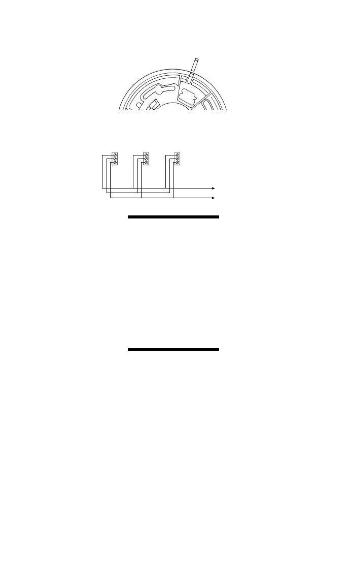
INTERCONNECTING
SMOKE ALARMS
•
Use #18 AWG minimum solid or stranded wire. When intercon-
necting, maximum wire length between any two is 1,500 feet for
#18 AWG or 4,000 feet for #14 AWG (20 OHMS loop resistance).
•
This smoke alarm may be interconnected with as many as
11 other Firex model AD, ADC, FX1218 and PAD smoke alarms,
or as many as 6 Firex model ADH heat alarms for a total of not
more than 18 interconnected devices. DO NOT connect to any
other type or model smoke alarm.
•
Connect smoke alarms to a single AC branch circuit. If local codes
do not permit, be sure the neutral wire is common to both phases.
RED AND GREEN LED INDICATORS
This smoke alarm features separate red and green LED indicators.
The LEDs indicate the following:
GREEN LED
ON — AC power is present.
OFF — AC power is not present.
RED LED — can be seen through the push to
test button.
Blinks once a minute — indicating normal operation.
Blinks once a second — smoke alarm senses smoke and
simultaneously sounds an audi-
ble alarm.
Blinks once every 10 seconds — smoke alarm is quieting an
unwanted alarm (Model ADC
only—ionization with False
Alarm Control™).
(Interconnected system only):
OFF — another smoke alarm in the network has sensed
smoke and is signalling this alarm.
 Loading...