D100305X012
Type
s 6
5
5 a
n
d 6
55
R A
ctuators
fo
r S
elf-Operate
d C
ontrol
Contents
Introduction
1.
. . . . . . . . . . . . . . . . . . . . . . . . . . . . . .
Scope of Manual 1.
. . . . . . . . . . . . . . . . . . . . . . . . . . . .
Description 2
. . . . . . . . . . . . . . . . . . . . . . . . . . . . . . . . . .
Specifications 2
. . . . . . . . . . . . . . . . . . . . . . . . . . . . . . .
Installation
2
. . . . . . . . . . . . . . . . . . . . . . . . . . . . . . . .
Actuator Mounting 3.
. . . . . . . . . . . . . . . . . . . . . . . . . .
Loading Connections 6.
. . . . . . . . . . . . . . . . . . . . . . . .
Startup
6
. . . . . . . . . . . . . . . . . . . . . . . . . . . . . . . . . . . .
Startup for Pressure-Reducing Service 6.
. . . . . . . . .
Startup for Pressure-Relief Service 6.
. . . . . . . . . . . .
Adjustment for Pressure-Reducing or
Pressure-Relief Service 6.
. . . . . . . . . . . . . . . . . . .
Shutdown
7
. . . . . . . . . . . . . . . . . . . . . . . . . . . . . . . . .
Maintenance
7
. . . . . . . . . . . . . . . . . . . . . . . . . . . . . .
Actuator 7
. . . . . . . . . . . . . . . . . . . . . . . . . . . . . . . . . . . .
Disassembly 7
. . . . . . . . . . . . . . . . . . . . . . . . . . . . . . .
Assembly 8
. . . . . . . . . . . . . . . . . . . . . . . . . . . . . . . . . .
Top-Mounted Handwheel 8.
. . . . . . . . . . . . . . . . . . . .
Disassembly 9
. . . . . . . . . . . . . . . . . . . . . . . . . . . . . . .
Assembly 9
. . . . . . . . . . . . . . . . . . . . . . . . . . . . . . . . . .
Parts Ordering
9.
. . . . . . . . . . . . . . . . . . . . . . . . . . .
Parts List
10.
. . . . . . . . . . . . . . . . . . . . . . . . . . . . . . . .
Introduction
Scope of Manual
This instruction manual provides installation, adjust-
ment, maintenance, and parts ordering for the Type
655 and 655R actuators and the top-mounted hand-
wheel. Refer to separate instruction manuals for in-
formation about valves and accessories used with
these actuators.
Only personnel qualified through training or experience
should install, operate, and maintain the Type 655 and
655R actuators. If you have any questions about these
instructions, contact your Fisher Controls sales office
or sales representative before proceeding.
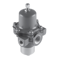
Figure 1. T
ype 655-ED Pressure-Reducing V
alve
Figure 2. T
ype 655 Actuator Nameplate
1F9408-E / DOC
W0466-1 / IL
Instruction Manual
Form 1292
October 1997
Type 655 and 655R