Paragraph 47
FORD
ENGINE BALANCER
Model 2110
47.
To remove balancer assembly,
first drain engine oil. If equipped with
front wheel drive, remove front axle and
drive shaft. Remove engine oil pan.
Remove balancer bottom cover (9-Fig.
96).
Remove balancer mounting cap
screws, then lower balancer assembly
from engine. Note that hollow dowels (6)
are used to position balancer on engine
block and may restrict removal of
balancer. Retain shims (7), if used, for
use in installation.
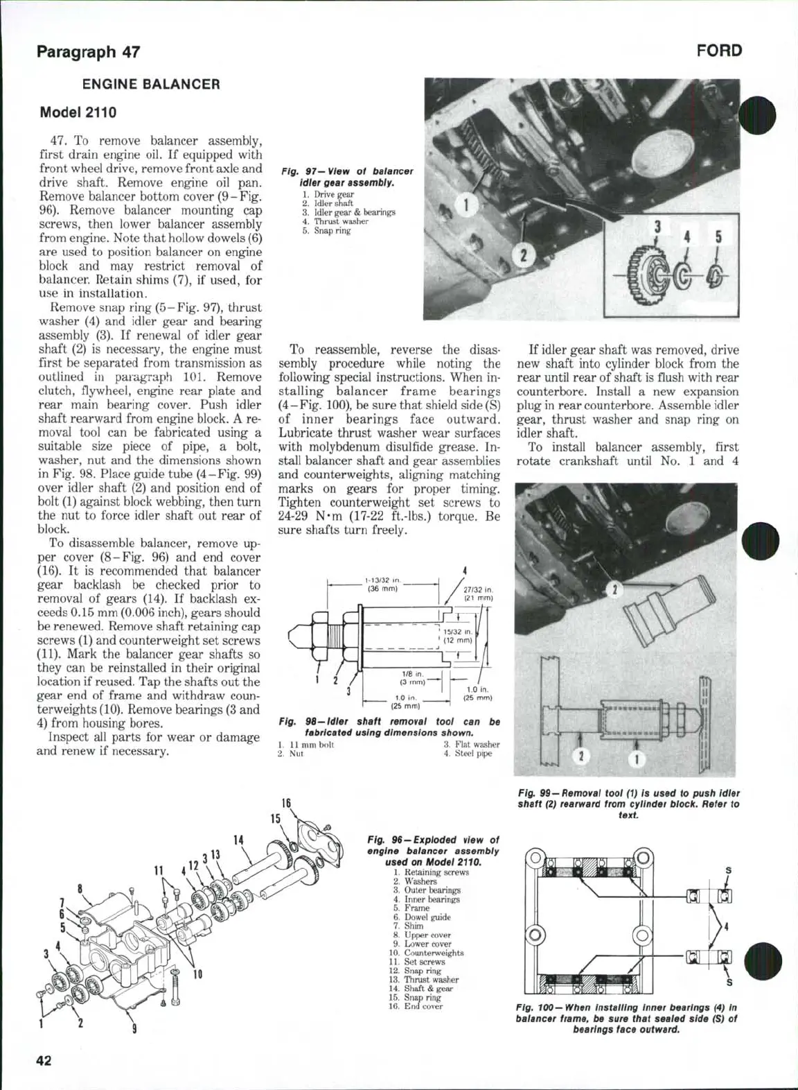
Remove snap ring
(5
- Fig, 97), thrust
washer (4) and idler gear and bearing
assembly (3), If renewal of idler gear
shaft (2) is necessary, the engine must
first be separated from transmission as
outlined in paragraph 101. Remove
clutch, flywheel, engine rear plate and
rear main bearing cover. Push idler
shaft rearward from engine block. A re-
moval tool can be fabricated using a
suitable size piece of pipe, a bolt,
washer, nut and the dimensions shown
in Fig. 98. Place guide tube (4-Fig, 99)
over idler shaft (2) and position end of
bolt (1) against block webbing, then turn
the nut to force idler shaft out rear of
block.
To disassemble balancer, remove up-
per cover (8-Fig. 96) and end cover
(16).
It is recommended that balancer
gear backlash be checked prior to
removal of gears (14). If backlash ex-
ceeds 0,15 mm (0.006 inch), gears should
be renewed. Remove shaft retaining cap
screws (1) and counterweight set screws
(11).
Mark the balancer gear shafts so
they can be reinstalled in their original
location if reused. Tap the shafts out the
gear end of frame and withdraw coun-
terweights
(10).
Remove bearings
(3
and
4) from housing bores.
Inspect all parts for wear or damage
and renew if necessary.
Fig. 97-View of balancer
Idler gear assembly.
1.
Drive gear
2.
Idler shaft
3.
Idler gear & bearings
4.
Thrust washer
5.
Snap ring
To reassemble, reverse the disas-
sembly procedure while noting the
following special instructions. When in-
stalling balancer frame bearings
(4-Fig. 100), be sure that shield side (S)
of inner bearings face outward.
Lubricate thrust washer wear surfaces
with molybdenum disulfide grease. In-
stall balancer shaft and gear assemblies
and counterweights, aligning matching
marks on gears for proper timing.
Tighten counterweight set screws to
24-29 N-m (17-22 ft.-lbs.) torque. Be
sure shafts turn freely.
1.0
in.
(25
mm)
Fig, 96—Idler shaft removal tool can be
fabricated using dimensions shown,
1.
11 mm bolt 3. Flat washer
2.
Nut 4. Steel pipe
If idler gear shaft was removed, drive
new shaft into cylinder block from the
rear until rear of shaft is flush with rear
counterbore. Install a new expansion
plug in rear counterbore. Assemble idler
gear, thrust washer and snap ring on
idler shaft.
To install balancer assembly, first
rotate crankshaft until No. 1 and 4
Fig.
99 —
Removal tool (1) Is used to push Idler
shaft
(2)
rearward from cylinder block. Refer to
text
Fig, 96-Exploded view of
engine baiancer assembly
used on Model 2110.
1.
Retaining screws
2.
Washers
3.
Outer bearings
4.
Inner bearings
5.
Frame
6. Dowel guide
7.
Shim
8. Upper cover
9. Lower cover
10.
Counterweights
11.
Set screws
12.
Snap ring
13.
Thrust washer
14.
Shaft
&
gear
15.
Snap ring
16.
End cover
S
Fig, 100-When installing Inner bearings (4) In
balancer frame, be sure that sealed side (S) of
bearings face outward.
 Loading...


