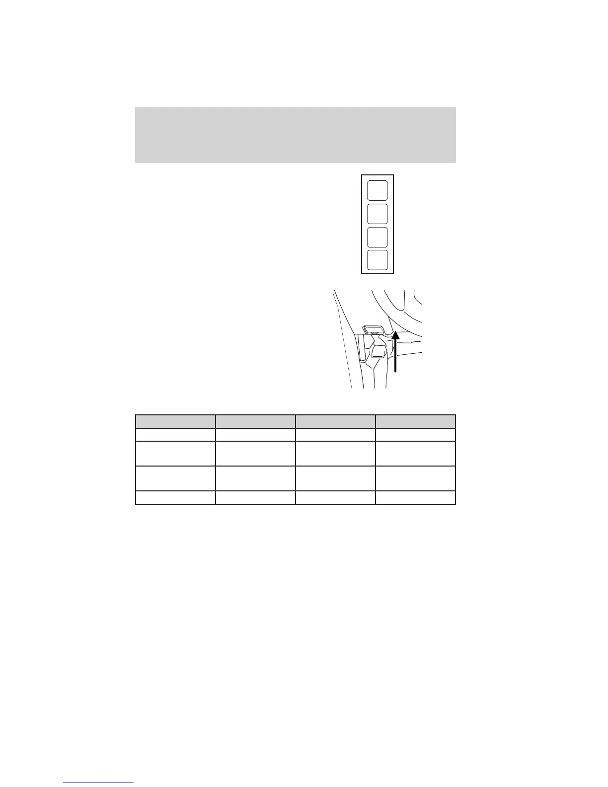
The relays are coded as shown in
the accompanying illustration.
There will also be one power lead
for each switch found as a blunt-cut
and sealed wire located below the
instrument panel and to the left of
the steering column.
They are coded as follows:
Switch Circuit number Wire color Fuse
AUX 1 CAC05 Yellow 25A
AUX 2 CAC06 Green with
Brown Trace
25A
AUX 3 CAC07 Violet with
Green Trace
10A
AUX 4 CAC08 Brown 15A
More detailed information about Upfitter switches can be found at
https://www.fleet.ford.com/truckbbas/.
RELAY
1
RELAY
2
RELAY
3
RELAY
4
Driver Controls
113
2011 F-250/350/450/550 (f23)
Owners Guide, 3rd Printing
USA (fus)
 Loading...