Esc Enter
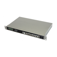
DMZ2DMZ1INTERNAL WAN1 WAN2CONSOLE USB
1 2 3 4
A
Straight-through Ethernet cables connect
to Internet (public switch, router, or modem)
Optional Ethernet connection to 1 or 2
DMZ networks
Straight-through Ethernet cables
connect to computers on internal network
Optional RJ-45 serial cable connects to management computer
Power cable connects to power outlet
Connector Type Speed Protocol Description
Internal RJ-45 10/100 Base-T Ethernet A 4-port switch connection for up to four network
devices or the internal network.
WAN1 and
WAN2
RJ-45 10/100 Base-T Ethernet Redundant connections to the Internet.
DMZ1 and
DMZ2
RJ-45 10/100 Base-T Ethernet Optional connections to one or two DMZ networks,
or to other FortiGate-200A units for high availability
(HA). For details, see the Documentation CD-ROM.
Console RJ-45 9600 Bps RS-232 Optional connection to the management computer.
Provides access to the command line interface
(CLI).
USB USB USB Optional connection for the FortiUSB key, modem or
backup operation.
Place the unit on a stable surface. It requires 1.5 inches (3.75 cm) clearance above and
on each side to allow for cooling.
Make sure the power switch on the back of the unit is turned off before connecting the
power and network cables.
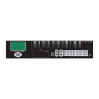
The following is displayed on the LCD when the unit is up and running:
Menu [ Fortigat -> ]
NAT, Standalone
•
•
•
Connect the FortiGate unit to a power outlet and to the internal and external networks.
Before beginning to congure the FortiGate unit, you need to plan how to integrate the unit into your network. Your conguration plan depends on the operating mode you select: NAT/Route
mode (the default) or Transparent mode.
NAT/Route mode
In NAT/Route mode, each FortiGate unit is visible to the network that it is connected to. All of
its interfaces are on different subnets. Each interface that is connected to a network must be
congured with an IP
address that is valid for
that network.
You would typically use
NAT/Route mode when the
FortiGate unit is deployed
as a gateway between pri-
vate and public networks.
In its default NAT/Route
mode conguration, the
unit functions as a rewall.
Firewall policies control
communications through
the FortiGate unit.
No trafc can pass through the FortiGate unit until you add rewall policies. In NAT/Route
mode, rewall policies can operate in NAT mode or in Route mode. In NAT mode, the
FortiGate unit performs network address translation before IP packets are sent to the
destination network. In Route mode, no translation takes place.
Transparent mode
In Transparent mode, the FortiGate unit is invisible to the network. All of its interfaces are on
the same subnet. You only have to congure a management IP address so that you can make
conguration changes.
You would typically use the
FortiGate unit in Transparent
mode on a private network
behind an existing rewall or
behind a router. In its default
Transparent mode conguration,
the unit functions as a rewall.
No trafc can pass through the
FortiGate unit until you add
rewall policies.
You can connect up to four network segments to the FortiGate unit to control trafc between
these network segments.
Refer to the Documentation CD-ROM for information on how to control trafc, and how to congure HA, antivirus protection, FortiGuard, Web content ltering, Spam ltering,
intrusion prevention (IPS), and virtual private networking (VPN).
FortiGate-200A
01-30002-0070-20060705
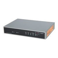
LED State Description
Power
Green The FortiGate unit is on.
Off The FortiGate unit is off.
Internal
WAN1
WAN2
DMZ1
DMZ2
Amber The correct cable is in use and the connected
equipment has power.
Flashing Amber Network activity at this interface.
Green The interface is connected at 100Mbps.
Off No link established.