Updated 6.11.2020 © Copyright 2020 Franklin Electricwww.franklin-controls.com
|
800.962.3787
| 310 Sequoia Parkway, Canby, Oregon 97013
indicates an imminently hazardous situation which, if not avoided, will
result in death or serious injury. This signal word is to be limited to the
most extreme situations.
indicates a potentially hazardous situation which, if not avoided, could
result in death or serious injury.
indicates a potentially hazardous situation which, if not avoided, may
result in minor or moderate injury. It may also be used to alert against
unsafe practices.
This is the safety alert symbol. Read and follow instructions carefully to
avoid a dangerous situation.
This symbol alerts the user to the presence of “dangerous voltage”
inside the product that might cause harm or electrical shock.
DANGER
WARNING
CAUTION
Safety Instructions
Equipment starts automatically. Lockout/tagout before servicing.
As with all electrical products, read manual thoroughly. Only qualified,
expert personnel should perform maintenance and installation. Contact the
nearest authorized service facility for examination, repair, or adjustment.
Do not disassemble or repair unit unless described in this manual; death
or injury to electrical shock or fire hazard may result. Specifications and
manual data subject to change. Consult factory for additional information.
DANGER
CAUTION
L1 L2/N
T1 T2
M
Voltage Input
Auto Run
Fault
Status
Output
Dry Input
Auto Run
Input
12-120V
Input
Main Power Wiring
Wire main power input and output to the appropriate 12AWG wire leads utilizing
properly sized wire nuts. Use only copper conductors rated at least 60°C.
Maintain proper clearances and verify that no possibility of an electrical short
exists between the power conductors or enclosure. Ensure that wires are not
under stress and all insulation is intact.
Low Voltage Wiring
Automation system control wiring should be run in a separate conduit. The
control terminals accept 26~14AWG wire torqued to 3.5 in-lb.
Installation
FAILURE TO FOLLOW THESE INSTRUCTIONS MAY RESULT IN DEATH OR
SERIOUS INJURY
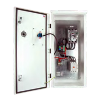
Mounting
Mount the starter on a minimum 14 cu-in single gang junction box. To access
mounting holes, slide upper and lower covers to the open position.
(See Figure 1)
Using provided mounting screws (6-32 x 7/8”), attach starter housing to junction
box (once appropriate wiring has been completed).
•
materials. Contact arcing can induce explosion or fire.
gnitnuom efaS .ylno snoitacol etairporppa )1 AMEN( 1 epyT LU ni retrats llatsnI •
requires a dry, protected environment.
• The BAS-1P is rated for maximum ambient temperature of 40°C
.erusolcne retne ot noitallatsni morf sirbed ro sgnivahs latem yna wolla ton oD •
WARNING
Figure 1
HAZARDOUS VOLTAGE
.tnempiuqe gnicivres ro gnillatsni erofeb rewop lla tuo kcol dna tcennocsiD •
ecivres ot roirp secruos rewop elpitlum tuo gnikcol eriuqer yam tnempiuqe sihT •
dna lacirtcele lanoitan & lacol elbacilppa lla htiw ecnadrocca ni eriw dna llatsnI •
construction codes
Installation & Operation Guide
LIT-12013012
Thank you for purchasing the Franklin Electric
Single Phase Building Automation Starter!
Please read this manual thoroughly to ensure
safe installation and proper operation.
Precautions
To prevent injury and property damage, follow these instructions.
Failure to adhere to installation/operation procedures and all applicable
codes may result in hazards as indicated by warning
codes outlined below: