INSTALLATION AND SERVICE MUST BE PERFORMED BY A QUALIFIED INSTALLER.
iMPORTANT: SAVE FOR LOCAL ELECTRICAL INSPECTOR"SUSE.
READ AND SAVE THESE INSTRUCTIONS FOR FUTURE REFERENCE.
If the information in this manual is not followed exactly, a fire
or explosion may result causing property damage, personal injury or death.
FOR YOUR SAFETY:
-- Do not store or use gasoline or other flammable vapors and liquids in the
vicinity of this or any other appliance.
-- WHAT TO DO IF YOU SMELL GAS:
• Do not try to light any appliance.
Do not touch any electrkal switch; do not use any phone in your building.
Immediately call your gas supplier from a neighbor's phone. Follow the
gas supplier"s instructions.
If you cannot reach your gas supplier, call the fire department.
-- Installation and service must be performed by a qualified installer, service
agency or the gas supplier.
Refer to your serial plate for
applicable agency certitication
Appliances Installed in the
state of Massachusetts:
This Appliance can only
be installed in the state of
Massachusetts by a Massachusetts
licensed plumber or gasfitter.
This appliance must be installed
with a three (3) foot / 36 in. long
flexible gas connector.
A"T" handle type manual gas
valve must be installed in the gas
supply line to this appliance.
_LL
30" Min.
(76.2 cm Min.
Shave
Raised
Edge
to Clear
Space
fora 31_/2
(81 cm) Wide
Cooktop.
1 1/2"Max.
(3.8cm Max.)
I
Locate Cabinet Doors
1" (2.5 cm) Min. from
Cutout Opening.
These su traces
should be
fiat
(hatched
5" Min.
(12.7 cm Min.)
From Wall Both Sides
31 1/2"
(81 cm)
30" Min. (76.2 cm)
Min. (see Note 3)
18" Min.
(45.7 cm) Min.
Exact
/ Approx. 1 718"(4.8 cm)
F
13"
(33 cm)
.......... 24" Min.
-' (61 cm Min.)
Grounded Jonction Box or Wall Outlet Should Be
Located 8" to 17" (20.3 cm to 43.2 cm) From Right
Cabinet and 2" to 4" (5.1 cm to 10.2 cm) From Floor.
Do not install the unit in the cabinet before reading next page.
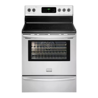
A. HEIGHT B. WIDTH C. COOKTOP D. TOTAL DEPTH TO E. CUTOUTWDTH***' F:CUTOUT G. HEIGHT
(under C0oktop) I ERQNi-QF RANGE (C0untert0p DEPTH OF COUNTERTOP
_ and Cabinet)
35 718" (91,1 cm) 30" (76,2cm) 31 1/2" 28 5/16" (71,9cm) 30_+1/16"
36 5/8" (93 cm) (80 cm) (76,2_+0,15 cm)
NOTE: Wiring diagram for these appliances are enclosed in this booklet.
Printed in United States
21 3/4" (55,2 cm) Min. 35 7/8" (91,1 cm) Min.
22 1/8" (56,2 cm) Max
24" (61 cm) Min. with 36 5/8" (93 cm) Max.
backguard
P/N318201690 (1007) Rev.A
English - pages 1-13
Espahol- p_iginas 14-26
Fran_ais - pages 27-39
Wiring Diagrams - pages 40