¢
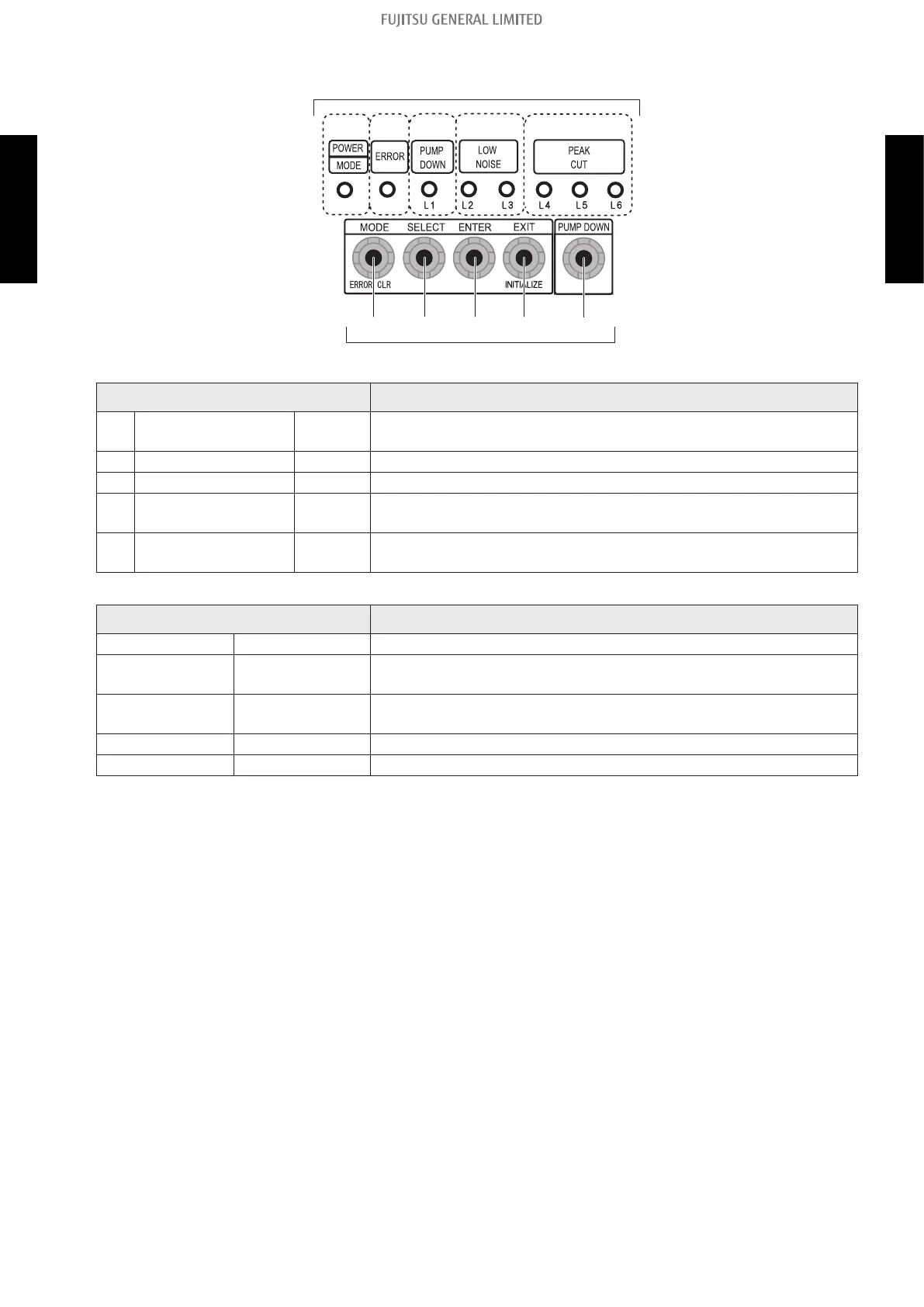
Switch buttons and the functions
S134
S133
S132 S131 S130
(1) (2) (3) (4) (5)
LED lamps
Switch buttons
LED lamp Function or operation method
(1) POWER/MODE Green
Lights on while power on.
Local setting in outdoor unit or error code is displayed with blink.
(2) ERROR Red Blinks during error operation.
(3) PUMP DOWN (L1) Orange Lights on during pump down operation.
(4)
LOW NOISE MODE
(L2 and L3)
Orange
Lights on during “Low noise mode” when local setting is activated.
(Lighting pattern of L2 and L3 indicates low noise level.)
(5)
PEAK CUT MODE
(L4, L5, and L6)
Orange
Lights on during “Peak cut mode” when local setting is activated.
(Lighting pattern of L4, L5, and L6 indicates peak cut level.)
Switch button Function or operation method
S134 MODE Switches between “Local setting” and “Error code display”.
S133 SELECT
Switches between the individual “Local settings” and the “Error code
displays”.
S132 ENTER
Switches between the individual “Local settings” and the “Error code
displays”.
S131 EXIT Returns to “Operation status display”.
S130 PUMP DOWN Starts the pump down operation.
- 102 -
13-1. Control PCB and switch buttons location
13. Function settings (30-45 models)
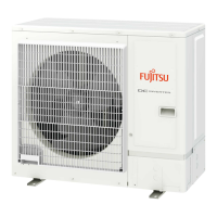
OUTDOOR UNIT
AOYG24-45KATA
OUTDOOR UNIT
AOYG24-45KATA
 Loading...