Fujitsu Trouble Shooting Guide
Current Models
Code Fault Diagnosis
E:0 I/U - R/C Comms Check R/C wiring. Interference?
E:01 I/U - O/U Comms Check intercon. wiring. Interference
E:02 Room Sensor Open Sensor Missing
E:03 Room Sensor Short Sensor Faulty
E:04 I/U Pipe Sensor Open Sensor Missing
E:05 I/U Pipe Sensor Short Sensor Faulty
E:06 O/U Pipe Sensor Open Sensor Missing
E:07 O/U Pipe Sensor Short Sensor Faulty
E:08 Power Source Error Incorrect Power Supply
E:09 Float Switch Check Drains - High Water Level
E:0A O/U Air Sensor Open Sensor Missing
E:0C Disch Sensor Open Sensor Missing
E:0D Disch Sensor Short Sensor Faulty
E:0F High Disch Temp Contamination In Pipework/
Gas Shortage
E:11 Model Abnormal Check PCB compatability
E:12 Indoor Fan Failure Check Fan and Motor
E:13 O/D Signal Abnormal Communications?
E:14 Outdoor PCB Fail PCB Failure
Fault LED1 LED2 LED3 LED4 LED5 LED6
Signal Failure Flash
Indoor Unit Failure Flash
Discharge Sensor Fail Flash
O/D Pipe Sensor Fail Flash Flash
O/D Air Sensor Fail Flash Flash
Power Source Error Flash
PCB Flash Flash Flash Flash Flash
PCB Failure All Flashing Very Rapidly
High Pressure Trip Flash
Discharge Temp Trip Flash
Unit Code Means:- Red Green Yellow
All Power On On Off Off
All Timer Mode On On Off
All Louvre On On On or Off On
All HP Defrost Cont. Long pulses Off Off
All Test Cont. Pulse Cont. Pulse Off
D,E,F Power Fail On Cont Long Pulses Off
All PCB Failure Cont. Short Pulse Cont. Short Pulse Off
G Room Sensor Fault 1 Short Pulse Rapid Pulse Off
A,B,G Sensor Fault 2 Short Pulses Rapid Pulse Off
D,E,F Room Sensor Open/Fail 2 Short Pulses Rapid Pulse Off
E,F Room Sensor Short 2 Short Pulses Rapid Pulse Rapid Pulse
C Room Sensor Fault 3 Short Pulses Long Pulse Off
D,E,F Pipe Sensor Open 3 Short Pulses Rapid Pulse Off
E,F Pipe Sensor Short 3 Short Pulses Rapid Pulse Rapid Pulse
D,E,F High Water 4 Short Pulses Rapid Pulse Off
F Comms Failure 5 Short Pulses Rapid Pulse Off
G High Water 6 Short Pulses Rapid Pulse Off
B,E,F Fan Failure 6 Short Pulses Rapid Pulse Off
F 3ph Reversal Rapid Pulse 2 Short Pulses Off
C Pipe Sensor Fault Long Pulse 3 Short Pulses Off
F OD Pipe Sensor Open Rapid Pulse 3 Short Pulses Off
F OD Pipe Sensor Short Rapid Pulse 3 Short Pulses Rapid Pulse
F OD Temp Sensor Open Rapid Pulse 4 Short Pulses Off
F OD Temp Sensor Short Rapid Pulse 4 Short Pulses Rapid Pulse
F Discharge Sensor Open Rapid Pulse 5 Short Pulses Off
F Discharge Sensor Short Rapid Pulse 5 Short Pulses Rapid Pulse
F High/Low Pressure Rapid Pulse 6 Short Pulses Off
F High Discharge Temp Rapid Pulse 7 Short Pulses Off
Sensor At 10°C At 20°C At 30°C
Air Temperature Sensors 20K Ohms 13K Ohms 8K Ohms
Indoor Pipe Sensor 103K Ohms 63K Ohms 40K Ohms
Outdoor Pipe Sensor 10K Ohms 6K Ohms 4K Ohms
Discharge Sensor 646K Ohms 395K Ohms 250K Ohms
Wired Controllers – Fault diagnostics
A Fault Condition is signalled by EE:EE appearing on the
LCD panel. The unit should be interrogated by switching it
off on the handset then pressing either the down arrows on
the SET TIME and TEMP/DAY buttons together for 3 seconds
for 7 day models or the ENERGY SAVE & ZONE CONTROL
buttons for other models. The Failure code is in 2 parts –
Fault and Address. The Fault Code is an E code. The second
is the unit address for multi linked systems – with single
units this is always 00. 7 day models have the fault code as
shown in the table below above the address. Other models
have the codes below, minus the 0, followed by the address –
e.g. E9:00 denoting Float Switch on Unit 0.
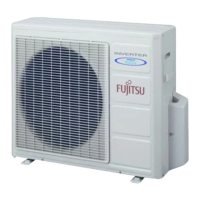
Outdoor Unit with
A fault condition is signified by flashing red LED’s on the the
outdoorPCBifitisequippedwithone.Exceptformultisplits
and 2 LED models, the diagnostics are shown in the table on
the right. For 2 LED models flashing signifies sensor failure
and constantly lit indicates high discharge temperature.
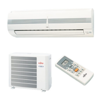
Models with wireless handsets
have three LED’s on the units
which light up to show operational,
or fault conditions. In general the
codes are as right, but there are
other codes available.
Model References are
A=ASY7A /R
B=ASY9/12A/R
C=ASY14 /17A /R
D=ASY20/30/A/R
ABY14-24A/R & AUY12/18AG/RG
E=ABY36/45A
F=ABY36/45R
G=AUY18/45A
Wireless Remote Control Models – Diagnostics
Sensor Resistances – Use to Check Thermistors across the range
 Loading...