– 13 –
TROUBLESHOOTING GUIDE
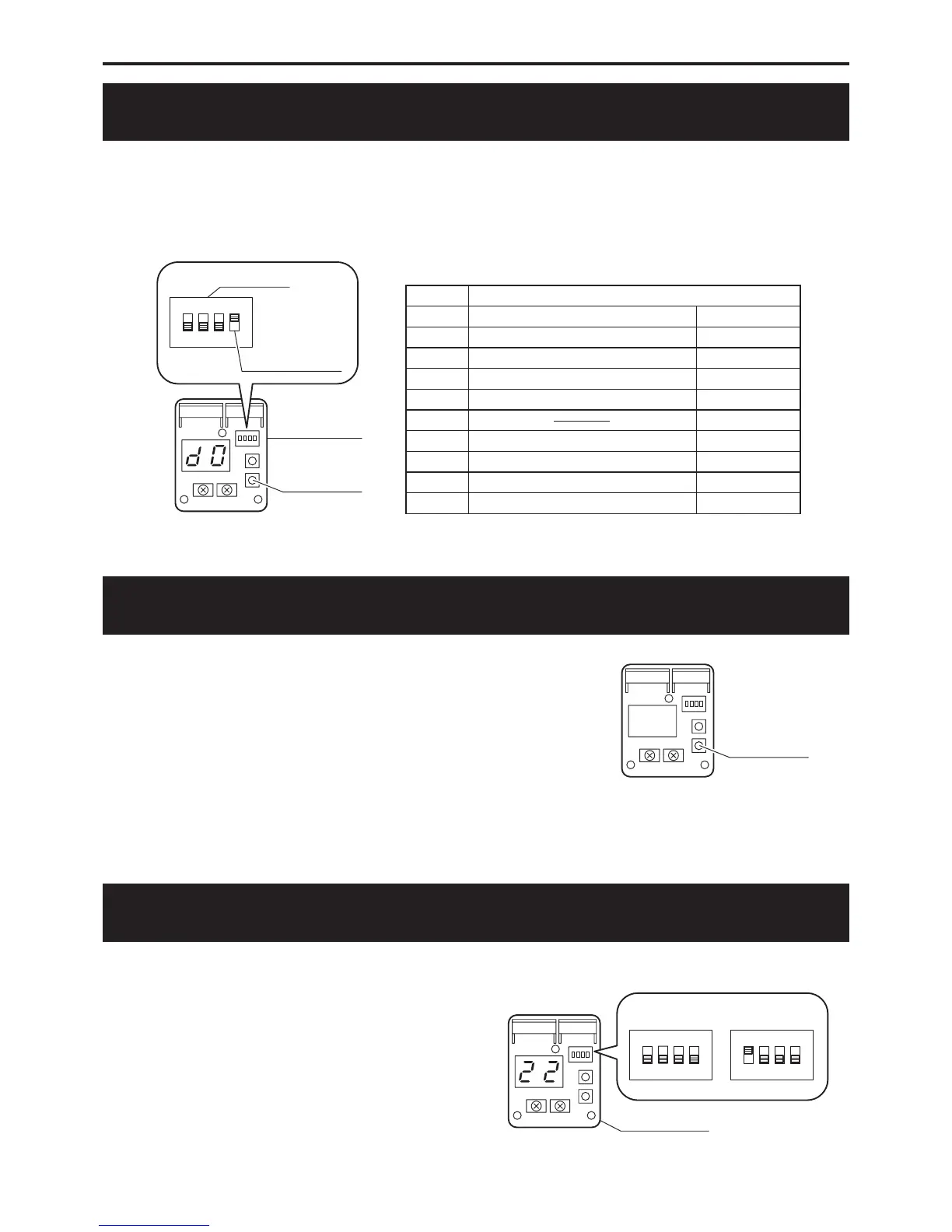
MONITOR DISPLAY METHOD
Switch “ ON ” the MODE SW. 4 on the unit PCB (DISPLAY). 1.
The monitor number and monitor data are alternately displayed.
Push the PUMP SW. of the unit PCB (DISPLAY). 2.
Every time the PUMP SW. is pressed the display changes in the sequence below.
Switch “ OFF ” the MODE SW. 4 after completing the check.3.
Monitor display contents •
Monitor Monitor data display contents
d0 Circulating water return temperature Units of 1°C
d1 Compressor operating frequency Units of 1Hz
d2 Discharge temperature Units of 1°C
d3 Power consumption value
Units of 100W
d4 Interface voltage Units of 0.1V
d5
d6 Ambient air temperature Units of 1°C
d7 External thermistor temperature Units of 1°C
d8 Suction temperature Units of 1°C
d9
Circulating water outgoing temperature
Units of 1°C
FREEZE PREVENTION SETTING
If the outside temperature falls below about 2°C, freeze pre- •
vention operation is possible depending on the unit MODE
SW. 1
1.No freeze prevention operation (When using anti-
freeeze)
2. Freeze prevention operation (When the outdoor
temperature falls below about 2°C , the circulating
water is warmed and circulated.)
CHARGE THE CIRCULATION WATER AND AIR PURGE IN WATER CIRCUIT
When you push PUMP SW on display PCB, the water pump is started to •
operate to circulate the water.
The each digital segment of right side on display PCB lights in sequence
during operating the pump.
The pump is automatically stopped after operating for 10 minutes. •
If it is not enough to let the air out of water circuit, please push PUMP SW
once again after the pump stopped.
When you would like to stop operating the pump before the pump is
automatically stopped, please push PUMP SW once again.
 Loading...