000-144-422
(5m) cable
supplied
w/BBFF1
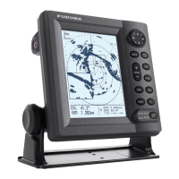
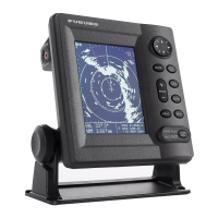
NAVNET QUICK SETUP GUIDE 10.4 inch series, single display (with optional equipment shown)
OR
cable included/attached
to the BBWGPS
Use supplied GP32 cable (I/O)
and part # 000-144-418 cable
to connect (see wiring configurations page)
12-24 VDC
BBFF1 SOUNDER
12-24 VDC
BBWGPS
000-125-237 cable
supplied with PG1000
or use a # 000-117-603
cable to connect to a
external heading device
Heading device (optional)
Furuno PG1000
OR
other external
(required for overlay)
AD10 Furuno format
required for ARP11
radar autoplotter option
FURUNO GP32
OR
other external GPS
(optional)
FURUNO
NavPilot 500
OR
other Autopilot
Radar antenna
connection
(GP 1900C, N/A)
BBWGPS (only configure if the BBWGPS antenna is connected to DATA1)
1. Press "MENU", Select [SYSTEM CONFIGURATION], Select [NAV OPTION]
2. Select [NAV SOURCE SETTINGS], Change POSITION SOURCE to [FURUNO BB GPS]
3. Press "RETURN"
4. Select [GPS SENSOR SETTINGS], Select [WAAS SETUP], Set [WAAS MODE], [ON]
5. Press "RETURN" twice
6. Select [SYSTEM SETUP], Select [PORT SETUP], Select [GPS/NMEA PORT] , Set FURUNO GPS SENSOR to [YES]
7. Press [RETURN], then [MENU] for normal operations
STEP 1
(Confirm no simulator modes are selected [SIM] would be displayed in upper left corner of display)
Connect the GPS position source. Use the Furuno BBWGPS antenna, Furuno GP32 or any compatible external device
(must output NMEA sentences GGA, VTG, ZDA, see manufacturer specifications).
RADAR SETUP PROCEDURES:
NOTE: Installation Menu access required.
Press and hold [MENU] while powering on display (starts normally)
Press [MENU], [SYSTEM CONFIGURATION], [INSTALLATION SETUP]
Press [RADAR SETUP] these are REQUIRED ADJUSTMENTS!
ANTENNA TYPE
A 1823C
B 1833 / 1833C
F 1933 / 1933C
G 1943 / 1943C
H 1953/C
ANTENNA ROTATION [ROTATE] (do not change)
TRANSMIT RADAR FOR 5 minutes prior to and continue for FOLLOWING
PROCEDURES (on the shortest range, set gain & sea control properly)
TUNING [OFF] Press [EDIT], select [ON], Press [ENTER], when complete
"NOW TUNING" disappears.
VIDEO ADJUST (important!) select [ON], press [ENTER], when complete "NOW
ADJUSTING VIDEO"disappears.
TIMING ADJUST [OFF] Press [EDIT], select [ON], visually select long straight
target, rotate knob to straighten target, Press [ENTER].
HEADING ADJUST (NOTE: factory setting 180° out for 24" dome antennas)
select [NEXT PAGE], HEADING ADJUST [OFF], Press [EDIT], select [ON], using
a range between 0.125-.25nm, rotate knob to bisect radar target, Press [SET]
Maximum radar ranges may need to be turned on using [MENU],
[RADAR RANGE SETUP] after "ANTENNA TYPE" is changed.
000-117-603
5m, cable
DATA 2
NETWORK
DATA 1
DATA 3
DATA 4
Connect the radar antenna to DJ1 of the radar display 1833C, 1933C, or
1943C. Also 1953C (see installation manual, PSU-005 section for more)
12-24 VDC
use the NavNet display "default" menu settings if connecting
an external GPS device (example: Furuno GP32 shown)
STEP 2
Applies to Radar only (Omit if installing a plotter)
POWER OFF then ON after any "MENU CHANGES" to store the new information.
Refer to the "Wiring configurations (10.4 inch display notes)" or "General Information" page for details
BBFF1(if installed): Displaying digital temperature and depth on NavNet display(s)
Press [MENU], [SYSTEM CONFIGURATION]
[GENERAL SETUP] (default is [NMEA] for displaying input from external depth and temperature devices)
TEMPERATURE SOURCE [ETR] (transducers with temperature sensor only)
DEPTH SOURCE [ETR]
Connect the BBFF1 network sounder to the display "network port" using the
supplied blue 000-144-422, 5m network cable
STEP 3
BBFF1 Network sounder if Installed (Plug and Play)