24
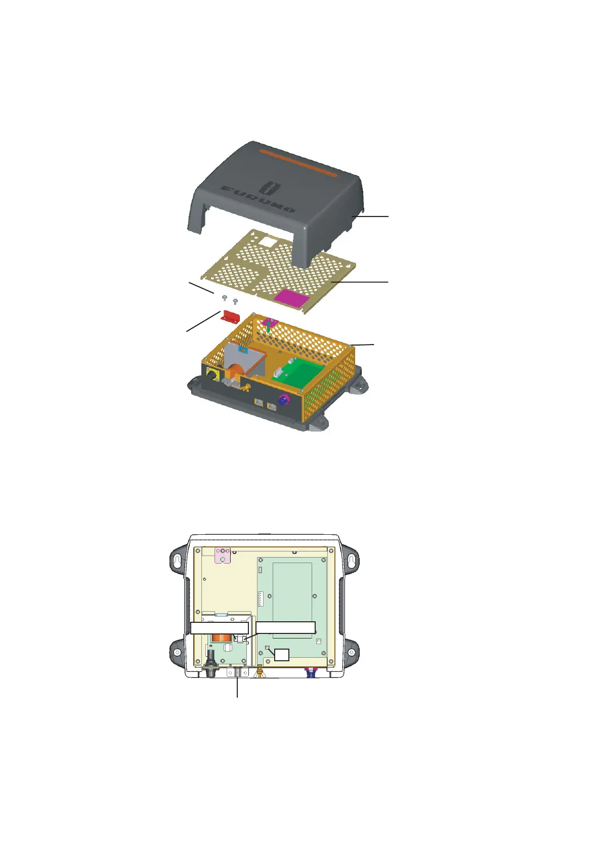
2.3.2 Wiring inside power supply unit PSU-012 (Option)
1. Detach the body cover by hand.
2. Loosen six pan head screws (M3x8) and slide the shield cover upward to remove it.
3. Unfasten two pan head screws (M4x12) to remove the cable clamp.
4. Connect the cable VL3P-VV-S2X2C-AA050 (supplied) to the power connector in the PSU-
012.
Note:
When the power supply unit is connected to TZT9/14/BB, attach the XH
Connector Assembly (supplied with PSU-012) to J7 on the PWR board. For
details, see "How to connect TZT9/14/BB" (supplied with PSU-012).
5. Remount the cable clamp, shield cover and body cover in that order.
6. Connect other cables.
Body cover
Shield cover
Pan head screw
(M3x8, 6 pcs.)
Pan head screw
(M4x12, 2 pcs.)
Cable clamp
For white wire
For black wire
Put the cable VL3P-VV-S2X2C-AA050 here at the shield part.
J7

 Loading...