3. Connect the other end of the ground wire to the ground location on the boat.
4. Route the appropriate gauge of wire to the amplifier and to the boat battery, and select an option:
• Install a properly rated in-line fuse on the power wire as close to the battery as possible.
• Identify or install a circuit breaker, as close to the battery as possible, for use with the amplifier power wire.
NOTICE
You must not connect the power wire to the amplifier and battery or circuit breaker before you complete all of the other connections. Connecting the amplifier to power before you
complete all of the other connections may cause damage to your audio system.
5. Select an option:
• If your stereo has an amplifier turn-on wire, route a 20 AWG (0.52 mm ²) wire from the amplifier turn-on wire on the stereo to the amplifier.
NOTE: The amplifier and the stereo must connect to the same physical ground location for the amplifier turn-on signal to function properly.
• If your stereo does not have an amplifier turn-on wire, route a 20 AWG (0.52 mm ) wire from the positive terminal of the battery, through a switch, to the amplifier.
6. Using the included 2.5 mm hex key, connect the 20 AWG (0.52 mm 2 ) wire to the REM terminal on the amplifier.
Make all of the other connections to the stereo and speakers before completing the connection to power (Completing the Connections, page 4).
Power Cable Gauge Guide
You should use 4 AWG (21.1 mm² ) wires for most installations. If your total amperage is higher than 50–65 A, and your cable run is longer than 10–13 ft (3–4 m), you can use these
tables to determine if you need to use a larger gauge of wire. This table accounts for terminal connection resistance.
NOTE: If you are using aluminum wire, you should use a wire two gauges larger than the gauge listed below to compensate for a potential voltage drop due to the wire material.
Total Amperage 0-4 ft. (0-1.2 m) 4-7 ft. (1.2-2.1 m) 7-10 ft. (2.1-3 m) 10-13 ft. (3-4 m)
85-105A
4AWG (21.1 mm
2
) 4AWG (21.1 mm
2
) 4AWG (21.1 mm
2
) 2AWG (33.6 mm
2
)
105-125 A
4 AWG (21.1 mm
2
) 4 AWG (21.1 mm
2
) 4 AWG (21.1 mm
2
) 2 AWG (33.6 mm
2
)
125-150 A
2 AWG (33.6 mm
2
) 2 AWG (33.6 mm
2
) 2 AWG (33.6 mm
2
) 0 AWG (53.5 mm
2
)
Total Amperage 13-16 ft. (4-4.9 m) 16-19 ft.(4.9-5.8 m) 19-22 ft. (5.8-6.7 m) 22-28 ft. (6.7-8.5 m)
50-65A
4AWG (21.1 mm
2
) 4AWG (21.1 mm
2
) 4AWG (21.1 mm
2
) 2AWG (33.6 mm
2
)
65-85A
2AWG (33.6 mm
2
) 2AWG (33.6 mm
2
) 2AWG (33.6 mm
2
) OAWG (53.5 mm
2
)
85-105A
2AWG (33.6 mm
2
) 2AWG (33.6 mm
2
) 2AWG (33.6 mm
2
)
OAWG (53.5 mm2)
105–125 A
0 AWG (53.5 mm
2
) 0 AWG (53.5 mm
2
) 0 AWG (53.5 mm
2
) 0 AWG (53.5 mm
2
)
125–150 A
0 AWG (53.5 mm
2
) 0 AWG (53.5 mm
2
) 0 AWG (53.5 mm
2
) 0 AWG (53.5 mm
2
)
Signal and Speaker Connection Considerations
When connecting your stereo and speakers to the amplifier, observe the following considerations:
Each set of zone speaker terminals on the amplifier is paired to the RCA inputs for that zone.
Each channel supports a nominal 4 Ohm speaker load impedance and a 2 Ohm minimum speaker load impedance.
You can connect two speakers in parallel on a single channel, and the combined impedance must be greater than the 2 Ohm minimum load impedance (Connecting Multiple
Speakers or Subwoofers In Parallel, page 3).
You can connect either a zone line out or a subwoofer line out from the stereo to any of the zone RCA inputs on the amplifier.
You should use the proper gauge speaker wire noted in the Speaker Wire Gauge Guide, page 3 to connect speakers and subwoofers to the amplifier.
You should observe the zone and polarity markings for each channel when connecting speakers to the amplifier. For example, Z1L indicates the ZONE 1 left channel, and Z1R
indicates the ZONE 1 right channel.
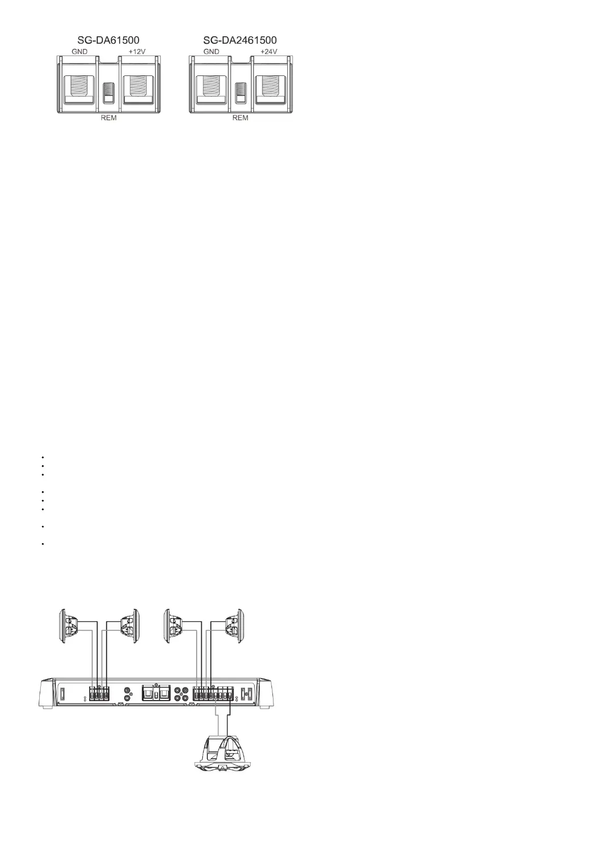
If you are connecting a combination of speakers and a subwoofer to the amplifier, you should connect the subwoofer to ZONE 3 as illustrated below. This zone has a dedicated
BASS BOOST control.
You can connect a subwoofer to a single channel, but you should connect it using bridge mode to get the best performance (Connecting a Speaker or Subwoofer in Bridge
Mode, page 3).
In the following example, a single 4 Ohm subwoofer is connected to the bridged terminals for ZONE 3, and pairs of 4 Ohm speakers are connected to the right and left channels for the
other two zones.
In this example, you must connect the subwoofer line out from the stereo to the Z3L and Z3R RCA connectors on the amplifier (using an RCA splitter), you must connect the two-zone
line out connectors from the stereo to the other two zones RCA connectors on the amplifier.
Speaker Wire Gauge Guide
You should use 16 AWG (1.31 mm
2
) speaker wires for most installations. You can use this table to determine if you need to use a larger gauge of wire. This table accounts for terminal
connection resistance.
NOTE: If you are using aluminum or tinned wire, you should use a wire two gauges larger than the gauge listed below to compensate for a potential voltage drop due to the wire
 Loading...