Home
Garmin
Autopilot System
G1000 NXi
Garmin G1000 NXi Service Manual
5
of 1
of 1 rating
403 pages
Give review
Manual
Specs
To Next Page
To Next Page
Loading...
190
-
00716
-
N1
2017
Revision 1
System M
aintena
nce Man
ual
King Air 300 Seri
es
Includes
Inst
ructions for Continued Air
worthiness
for STC SA01535WI
-D
2
Table of Contents
Table of Contents
4
Introduction
14
Content, Scope, Purpose
14
Organization
15
Definitions/Abbreviations
16
Units of Measure
17
Publications
17
Table 1-1, Required Documents
17
Table 1-2, Reference Publications
18
Revision and Distribution
19
System Description
20
Equipment Descriptions
20
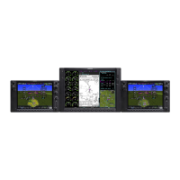
Figure 2-1, Display Units
21
Figure 2-2, Flight Stream 510
22
Figure 2-3, Audio Panel
22
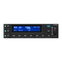
Figure 2-4, AFCS Controller
23
Figure 2-5, FMS Controller
23
Figure 2-6, Transponders
24
Figure 2-7, GIA Unit
26
Figure 2-8, GEA Unit
26
Figure 2-9, GSU-75B ADAHRS with Connector and Mounting Tray
27
Figure 2-10, GDC 7400 Air Data Computer
28
Figure 2-11, OAT Probe
28
Figure 2-12, AHRS
29
Figure 2-13, Magnetometer
30
Figure 2-14, GDL 69A/69A SXM Datalink
30
Figure 2-15, GDL 59 Wi-Fi Datalink
31
Figure 2-16, GSR 56 Satellite Receiver
31
Figure 2-17, GSD 41 Data Concentrator
32
Figure 2-18, GTS 820/850 Traffic System
32
Figure 2-19, GTS Traffic Processor
33
Figure 2-20, Weather Radar
33
Figure 2-21, Servo
34
Figure 2-22, GSA 9000 / GSM 9100
34
Figure 2-23, GRA 5500 Radar Altimeter
34
Figure 2-24, MD 302 Standby Attitude Module
35
G1000 Optional Interfaces
36
Electrical Power Distribution
37
Figure 2-25, 300 Series Electrical Distribution (Post G1000 STC)
38
Figure 2-26, G1000 Component Power Sources
39
Electrical Load Utilization
40
Table 2-1, Electrical Loads
40
Pitot/Static System
48
Figure 2-27, Pitot/Static System with ADC(S) and AHRS(S) Installed
48
Figure 2-28, Pitot/Static System with GDU 75B ADAHRS(S) Installed
49
Shield Block Grounds
50
G1000Nxi /GFC700 Block Diagrams
50
Figure 2-29, G1000Nxi/Gfc 700 Block Diagram with GSU 75B ADAHRS
50
Figure 2-30, G1000Nxi/Gfc 700 Block Diagram with Separate ADC and AHRS
51
GDU 1050A and GDU 1550 Displays
52
Figure 2-31, GDU 1050A Control Interface
52
Figure 2-32, GDU 1550 Control Interface
52
Softkeys
53
FMS Knob
53
Figure 2-33, G1000 Softkeys
53
GCU 477 - MFD Controller
54
GMC 710 - AFCS Controls
54
Figure 2-34, MFD Controls (GCU 477 Shown)
54
Figure 2-35, AFCS Controls (GMC 710 Shown)
54
GMA 1347D Audio Panel
55
Figure 2-36, GMA 1347D Controls
55
G1000 Normal Mode
56
Reversionary Mode
57
Figure 2-37, Normal Mode
57
Figure 2-38, Automatic Reversion with MFD Failure
57
Figure 2-39, Manual Reversion with Pilot PFD Failure
57
Software and Configuration
58
Configuration Mode Overview
58
Figure 3-1, SET>ACTV Diagram
59
Figure 3-2, Loss of Communication
60
Figure 3-3, Configuration Status
60
Figure 3-4, Data Transmission Indicators
60
G1000 System Software Information
63
Figure 3-5, G1000 LRU Configuration File Storage
70
Figure 3-6, GSU/GRS/GDC Configuration Settings Storage
71
Configuration Mode
72
G1000 Hardware/Software Compatibility Check
72
Equipment Verification (Third Party/Optional Equipment Documentation)
73
Figure 3-7, Garmin Unit S/N Location
74
Figure 3-8, Garmin Unit Listed if Installed
75
Figure 3-9, Ethernet Connections Page
76
Figure 3-10, ESP Status Field
77
Configuration Checklist
78
G1000 Software/Configuration Procedure
80
Figure 3-11, Software/Configuration Overview
80
System Software and Configuration Load
81
Feature Enablement
89
Aircraft Registration Number Entry
97
Configuration Manager
99
Splash Screen Loading
99
Clearing Default User Settings
100
Database Loading
100
Figure 3-12, MFD aux - Database Page DB Transfer
101
Configuration of Navigation Map for Traffic System
102
Enter Flight ID for GTX 3000 Installations
102
GRA 5500 Legacy Software and Configuration (Non Integrated)
103
Interface Confirmation
106
Figure 3-13, Stormscope Configuration Page
106
Figure 3-14, Stormscope Configuration
106
MD 302 Configuration and Sensor Calibration
107
Instructions for Continued Airworthiness
112
Airworthiness Limitations
112
Servicing Information
113
Maintenance Intervals
116
Table 4-1, Maintenance Intervals
116
Table 4-2, Discontinued Maintenance Intervals
121
Visual Inspection
122
Table 4-3, Nose Section Visual Inspection Procedure
122
Table 4-4, Nose Avionics Compartment Visual Inspection Procedure
122
Table 4-5, Pilot's Compartment Visual Inspection Procedure
123
Table 4-6, Instrument Panel G1000 Equipment Visual Inspection Procedure
124
Table 4-7, Cabin Area Visual Inspection Procedure
125
Table 4-8, Rear Fuselage and Empennage Visual Inspection Procedure
126
Electrical Bonding Test
127
Table 4-9, Lightning Strike Inspection Procedure
127
GSU 75B, GRS 77, or GRS 7800 Earth Magnetic Field Updates
130
GSA 80 Greasing Procedure
130
Flaps-In-Motion Discrete Input Check
131
Figure 4-1, GIA I/O Page
131
Figure 4-2, Discrete Indications
131
GSM 86 Slip Clutch Torque Check Procedure
132
Figure 4-3, GFC Status Page
132
Table 4-10, GSM 86 Slip Clutch Torque Settings
134
G1000 Redundant Connection Check
135
Engine Data Check
139
Table 4-11, Engine Data Check Test Equipment
139
Table 4-12, ITT Indication Test Points
139
Figure 4-4, Ambient Temperature Conversion Chart
140
Trim Annunciator Check
141
Table 4-13, Torque Indication Test Points
141
G1000 Miscompare Checks
143
Nose Avionics Compartment Fans Operational Check
144
Instrument Panel Fans Operational Check
145
Standby Battery Periodic Checks
145
Table 4-14, Standby Battery Required Equipment
145
Figure 4-5, Standby Battery
146
Rudder Boost Operational Check
149
Figure 4-6, Power Supply Connection
149
Exterior Skin Inspection Around Antennas
150
Figure 4-7, Exterior Skin Inspection Around Antennas
150
Troubleshooting
151
Figure 5-1, aux - System Status Page
151
System Annunciations
152
Figure 5-2, System Annunciations
152
G1000 Alerting System
176
Figure 5-3, Alerts & Annunciations
176
Figure 5-4, Alerts Softkey Annunciation
176
Aural & Audio Alerts
177
King Air 300 Series Specific Alerts
179
TAWS Troubleshooting
180
Synthetic Vision and Pathways Troubleshooting
181
Table 5-1, SVS Troubleshooting
181
Table 5-2, SVS-Related Alert Messages
181
GFC 700 AFCS Troubleshooting
182
Figure 5-5, AFCS Annunciation Field
182
General Troubleshooting
183
Table 5-3, AFCS Annunciation Troubleshooting
183
Table 5-4, AFCS General Troubleshooting
184
Figure 5-6, GFC Status Page
185
Backup Communications Path Checks
195
GDU 105X Troubleshooting
195
GDU 105X Alerts
197
GIA 63 Troubleshooting
205
GIA Alert Messages
206
GEA Troubleshooting
212
GTX Troubleshooting
213
GDL 69A or GDL69A SXM Troubleshooting
214
GSU 75B, GRS 77, or GRS 7800 and GMU 44 Troubleshooting
216
Figure 5-7, Magnetometer Interference Test
219
Table 5-5, Magnetometer Interference Test Sequence
220
GSU 75B/GDC 7400 Troubleshooting
221
GWX 68 or GWX 70 Troubleshooting
222
GMC 710 Troubleshooting
223
GCU 477 Troubleshooting
224
Software/Configuration Troubleshooting
225
Backshell/Backplate Connectors
227
Figure 5-8, GIA 63W Backplate Connectors
227
Figure 5-9, GEA 71 Backplate Connectors
228
Figure 5-10, GMA 1347D Backplate Connectors
228
Figure 5-11, GTX 33/33D Backplate Connectors
228
Figure 5-12, GTX 3000 Connectors (P3301 and P3302)
229
Figure 5-13, GTX 335R/345R Looking at Front of Connector (P3251)
229
Figure 5-14, GTX 345R (Only) Looking at Front of Connector (P3252)
230
Figure 5-15, GDU 1050A/1550 Backshell Connector (P10401 or P15001)
230
Figure 5-16, GRS 77 Backshell Connector (P771)
230
Figure 5-17, GRS 7800 Backshell Connector (P78001)
231
Figure 5-18, GSU 75B Connector View from Front (P751)
231
Figure 5-19, GDC 7400 Mating Connector (P74001)
231
Figure 5-20, GDL 69A/GDL 69A SXM Backplate Connector (P69A1)
231
Figure 5-21, GCU 477 Backshell Connector (P4751)
232
Figure 5-22, GMC 710 Backshell Connector (P7101)
232
Figure 5-23, GWX 68 Backshell Connector (P681)
232
Figure 5-24, GWX 70 Backshell Connector (P751)
232
Figure 5-25, GTS 820/850 Mating Connectors (P8001 and P8002)
232
Figure 5-26, GTS 820/850 Mating Connector (P8003) (Rear View)
233
Figure 5-27, GTS Processor Connector (P8001)
233
Figure 5-28, GPA 65 Mating Connector (P651) (Rear View)
233
Figure 5-29, Signal Conditioner (1PVIB1 and 2PVIB1)
233
Figure 5-30, GDL 59 Mating Connector (1P591)
234
Figure 5-31, GSR 56 Mating Connector (1P561)
234
Figure 5-32, GRA 5500 Connector (P55001)
234
Figure 5-33, GSD 41 Backplate Connector (P411)
234
Figure 5-34, GSA 9000 Mating Connector (P90001)
234
Mechanical Standby Attitude Indicator Troubleshooting
235
Mechanical Standby Airspeed Indicator Troubleshooting
235
Mechanical Standby Altimeter Troubleshooting
236
MD 302 Standby Indicator Troubleshooting
236
GDL 59 Troubleshooting
237
GSR 56 Troubleshooting
237
GTS 820/850 Troubleshooting
237
GTS Traffic Processor Troubleshooting
239
Equipment Removal & Installation
241
Gdu 1050A/1550
242
GMA 1347D Audio Panel
242
GIA 63W Integrated Avionics Units
243
GEA 71 Engine/Airframe Unit
243
GTX 33( ) or GTX 3000 Transponder
244
GTX 335R/GTRX 345R Transponder
245
GDC 7400 Air Data Computer
245
GTP 59 OAT Probe
246
GRS 77 or GRS 7800 AHRS or GSU 75B ADAHRS
246
GMU 44 Magnetometer
247
GDL 69A or GDL 69A SXM
249
GSA 80 and GSA 9000 Servo Motors
249
Figure 6-1, GSA 80 Servo Gear
250
Figure 6-2, GSM 9100 O-Ring
250
Table
250
GSM 86 and GSM 9100 Servo Gearbox
251
Gcu 477
251
Gmc 710
251
GWX 68 or GWX 70
252
Configuration Modules
252
Figure 6-3, Configuration Module Installation
253
Table 6-1, Configuration Module Kit - 011-00979-00
253
Figure 6-4, GRS 7800 Configuration Module Installation
254
Table 6-2, GRS 7800 Configuration Module Parts
254
Figure 6-5, GSU 75B Configuration Module Installation
255
Table 6-3, GSU 75B Configuration Module Kit - 011-00979-20
255
GEA 71 Backshell Thermocouple Removal & Replacement
257
Figure 6-6, GEA Backshell Thermocouple
257
Table 6-4, Thermocouple Kit (011-00981-00)
257
GPS/WAAS Antennas
258
Diversity Transponder Antenna
258
Iridium Antenna
259
Wi-Fi Antenna
259
Signal Conditioners
260
Instrument Panel Annunciators (Prop Synch and Standby Battery)
260
Emergency Frequency Switch/Annunciator
261
L-3 Avionics (BF Goodrich) PS-835(C or D Model) Emergency Battery
261
MD 302 Standby Attitude Module (SAM)
261
Figure 6-7, MD 302 Backshell and Config Module
263
Mechanical Standby Indicators
264
GIA Cooling Fans
266
GDU Cooling Fans
266
GTS 820/850 and GTS Processor Traffic Units
267
GPA 65 PA/LNA Unit
267
GA 58 Traffic Antennas
268
GDL 59 Wi-Fi Datalink
268
GSR 56 Satellite Receiver
269
GRA 5500 Radar Altimeter
269
GSD 41 Data Concentrator
270
Garmin G1000 Lru Replacement/Configuration & Testing
271
Gdu 1050A/1550 Pfd & Mfd
271
Figure 7-1, G1000 Normal Mode Check
274
GMA 1347D Audio Panel
275
GIA 63W Integrated Avionics Unit
282
Figure 7-2, aux - GPS Status Page (MFD)
289
GEA 71 Engine/Airframe Unit
293
Figure 7-3, Normal Engine Instrument Markings (MFD)
296
Table 7-1, ITT Indication Test Points
298
Figure 7-4, Ambient Temperature Conversion Chart
299
Table 7-2, Torque Indication Test Points
300
Table 7-3, N1 Indication Test Points
301
Table 7-4, N2 Indication Test Points
303
Table 7-5, Fuel Flow Indication Test Points
304
Table 7-6, Oil Pressure Test Points
305
Table 7-7, Oil Temperature Test Points
306
GTX 335R, GTX 345R, GTX 33( ), or GTX 3000 Transponder
307
Figure 7-5, Aircraft Registration
309
Gsu 75B Adahrs
310
GDC 7400 Air Data
312
Table 7-8, Air Data System Test
315
Table 7-9, Vertical Speed Table
317
GRS 77 or 7800 AHRS and GMU 44 Magnetometer
318
GMU 44 Magnetometer
320
GSU/GRS/GMU Calibration Procedures
321
Table 7-10, Required GRS/GMU Calibrations
322
Figure 7-6, GRS/GMU Calibration, Pitch/Roll Offset
323
Figure 7-7, GRS/GMU Calibration, Engine Run-Up
327
Figure 7-8, Normal Mode AHRS Check
329
GDL 69A or GDL 69A SXM Data Link
330
GSA 80 Servos
332
GCU 477 FMS Controller
334
GMC 710 AFCS Controller
337
GWX 68 or GWX 70 Weather Radar
339
GRA 5500 Radar Altimeter
341
Garmin Traffic Systems (GTS 8XX/GTS 8XXX)
343
Gdl 59
348
Gsr 56
351
Gsd 41
352
Subsystem Functional Checks
354
Non-Garmin Traffic System Functional Check
354
Stormscope Functional Check
355
TAWS Functional Check
357
Flitecharts Functional Check
360
Chartview Functional Check
361
Safetaxi Functional Check
362
DME Functional Check
363
ADF Functional Check
364
GRA 5500 Radar Altimeter Functional Check
364
Non-Garmin Radar Altimeter Check (Optional)
364
Weight on Wheels and Low Speed Awareness Band Check
365
RVSM Checks
366
Figure 8-1, Low Speed Awareness Band Symbolization
366
Table 8-1, RVSM Required Avionics
367
Figure 8-2, RVSM Critical Region
368
Figure 8-3, RVSM Critical Region (Modified)
370
Figure 8-4, Dial Indicator
371
Figure 8-5, Static Port Measurement
371
Figure 8-6, Static Port Measurement Locations
372
Figure 8-7, Static Port Measurement Log
372
Table 8-2, In-Flight Altitude Hold Performance Test
373
ESP Functional Check
374
GTS Traffic System Functional Check
377
Figure 8-8, Traffic Map
377
Activation of Garmin Connext
380
GDL 59 Wi-Fi Data Link Functional Check
382
GSR 56 Satellite Receiver Functional Check
382
Figure 8-9, GSR56 Configuration Page
383
Figure 8-10, Aux-Telephone Page
383
Search and Rescue Functional Check
384
G1000 System Return to Service Procedure
385
Display Test
385
Figure 9-1, MFD Power up Page
385
Figure 9-2, PFD Power-Up System Annunciations
386
Figure 9-3, PFD Normal Operation
387
Display Failure Test
388
Reversion Mode Check
389
Figure 9-4, GDU Reversionary Mode
389
Cooling Fan Fail Annunciation Check
390
GPS Signal Acquisition
390
GPS Failure Test
391
Figure 9-5, AUX-GPS Status Page
391
GIA Failure Test
393
GEA Functional Check
394
Standby Instrument Electrical Power Checks
395
G1000 Backup Path Test
397
GFC 700 Ground Checkout
397
Maintenance Records
402
Other manuals for Garmin G1000 NXi
Supplemental Maintenance Manual
171 pages
Pilot's Guide
538 pages
Reference Guide
260 pages
Cockpit Reference Guide
270 pages
5
Based on 1 rating
Ask a question
Give review
Questions and Answers:
Need help?
Do you have a question about the Garmin G1000 NXi and is the answer not in the manual?
Ask a question
Garmin G1000 NXi Specifications
General
Manufacturer
Garmin
Display Type
LCD
Resolution
1024 x 768 pixels (XGA)
Power Supply
28 VDC
Operating Temperature
−20°C to +55°C
Related product manuals
Garmin GHC 10
26 pages
Garmin GHC 50
18 pages
Garmin GFC 500
44 pages
Garmin GFC 600
89 pages
Garmin TR-1 Gold
38 pages
Garmin GMC 7 Series
34 pages
Garmin TR-1 GOLD 906-2000-00
38 pages
Garmin GHP 12 Autopilot System
32 pages
GHP 10 Marine Autopilot System
26 pages
GHP 20 Marine Autopilot System with SmartPump
22 pages
Garmin Reactor 40
12 pages
Garmin Reactor 40 Kicker
28 pages