5–46 850 FEEDER PROTECTION SYSTEM – INSTRUCTION MANUAL
DEVICE CHAPTER 5: DEVICE, SYSTEM, INPUT AND OUTPUT SETPOINTS
Flex States
The Flex State feature provides a mechanism where any of 256 selected FlexLogic operand
states or any inputs can be used for efficient monitoring.
The feature allows user-customized access to the FlexLogic operand states in the relay.
The state bits are packed so that 16 states may be read out in a single Modbus register. The
state bits can be configured so that all of the states which are of interest are available in a
minimum number of Modbus registers.
Path: Setpoints > Device > Flex States
PARAMETER 1 (to 256)
Range: Off, Any FlexLogic operand
Default: Off
Front Panel
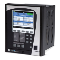
The relay provides an easy to use faceplate for menu navigation through 5 navigation
pushbuttons and high quality graphical display. Conveniently located on the panel is a
group of 7 pushbuttons for Up/Down value selection, “Enter” “Home”, “Escape”, “Help”, and
“Reset” functions or a group of 11 including the Up/Down/Left/Right buttons on the
membrane faceplate. The Rugged and Membrane faceplate includes 3 programmable
function pushbuttons and 12 programmable LEDs. The 10 PB Membrane faceplate
includes 10 programmable function pushbuttons and 12 programmable LEDs.
Please refer to Front Control Panel Interface.
FAST PATH:
The USB port on the Front Panel is intended for connection to a portable PC.
Programmable LEDs Path: Setpoints > Device > Programmable LEDs
LED “TRIP”
Range: Off, Any FlexLogic operand
Default: Any Trip
The setpoint requires assigning a FlexLogic operand to turn on the LED “TRIP”, when
triggered. This indicator always latches, and a reset command must be initiated to allow
the latch to be reset.
The LED can be also triggered by the operation of a protection, control, or monitoring
element with its function selected as “Trip”.
LED “ALARM”
Range: Off, Any FlexLogic operand
Default: Any Alarm
The setpoint requires assigning a FlexLogic operand to turn on the LED “ALARM”, when
triggered. The indicator is a self-reset indicator, unless it is initiated from a protection,
control, or monitoring element whose function is selected as “Latched Alarm”. Resetting
the Latched Alarm LED is performed by initiating a Reset command.
LED 5 (17) NAME
LED 5 (24) NAME
Range: Up to 13 alphanumeric characters
Default: LED 5
The setpoint is used to select the LED name by choosing up to 13 alphanumeric
characters.

 Loading...