Home
GE
Protection Device
D60
GE D60 User Manual
4
of 1
of 1 rating
826 pages
Give review
Manual
Specs
To Next Page
To Next Page
To Previous Page
To Previous Page
Loading...
5-278
D60 Line Distance
Pr
otection System
GE Multilin
5.7 CONTROL ELEMENTS
5 SETTINGS
5
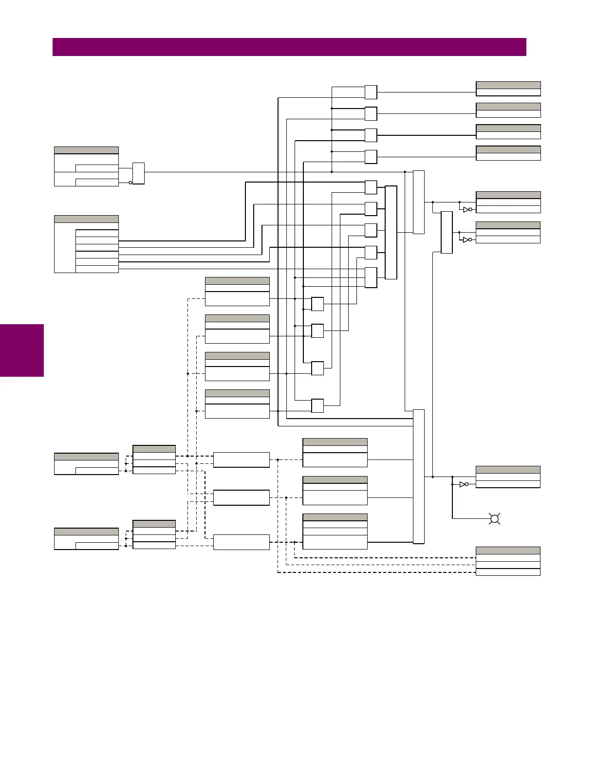
Figure 5–143: SYNCHROCHECK SCHEME LOGIC
Calculate
I V1 – V2 I = ΔV
AND
OR
AND
AND
Calculate
I Φ1 – Φ2 I =
Φ
Δ
Calculate
I F1 – F2 I = ΔF
SET
TI
N
G
None
L
V1 and DV2
Dead Source Select
DV1 and L
V2
DV1 or DV2
DV1 xor DV2
DV1 and DV2
SET
TI
N
G
V1 ≤
Maximum
Dead V1 Max Volt
SET
TI
N
G
V2 ≤
Maximum
Dead V2 Max Volt
SET
TI
N
G
= SRC 1
V1 Source
SET
TI
N
G
= SRC 2
V2 Source
SET
TI
N
G
V1 ≥
Minimum
Live V1 Min Volt
SET
TI
N
G
V2 ≥
Minimum
Live V2 Min Volt
SET
TI
N
GS
ΔF
≤
Maximum
Max Freq Diff
Freq Hysteresis
SET
TI
N
G
ΔΦ
≤
Maximum
Max Angle Diff
SET
TI
N
G
ΔV
≤
Maximum
Max Volt Diff
AND
OR
XOR
AND
AND
AND
AND
AND
827076AD.CDR
ACTUAL V
ALUES
Synchrocheck 1 ΔV
Synchrocheck 1 ΔΦ
Synchrocheck 1 ΔF
AND
SET
TI
N
GS
Enabled = 1
Function
Off = 0
Block
AND
AND
AND
AND
FLEXLOGIC OPERA
N
D
SYNC1 V2 ABOVE MIN
SYNC1 V1 ABOVE MIN
SYNC1 V1 BELOW MAX
SYNC1 V2 BELOW MAX
FLEXLOGIC OPERA
N
D
FLEXLOGIC OPERA
N
D
FLEXLOGIC OPERA
N
D
OR
FLEXLOGIC OPERA
N
DS
SYNC1 DEAD S OP
SYNC1 DEAD S DP
O
FLEXLOGIC OPERA
N
DS
SYNC1 CLS OP
SYNC1 CLS DPO
CALCULA
TE
Magnitude V1
Angle
Φ1
Frequency F1
CALCULA
TE
Magnitude V2
Angle
Φ2
Frequency F2
FLEXLOGIC OPERA
N
DS
SYNC1 SYNC OP
SYNC1 SYNC DPO
SYNCHROCHECK 1
411
413
Table of Contents
Default Chapter
3
Table of Contents
3
1 Getting Started
11
Important Procedures
11
Cautions and Warnings
11
Inspection Procedure
12
Ur Overview
13
Introduction to the Ur
13
Hardware Architecture
13
Software Architecture
14
Enervista Ur Setup Software
15
System Requirements
15
Installation
15
Configuring the D60 for Software Access
16
Using the Quick Connect Feature
19
Connecting to the D60 Relay
24
Setting up Cybersentry and Changing Default Password
25
Ur Hardware
27
Mounting and Wiring
27
Communications
27
Faceplate Display
27
Using the Relay
28
Faceplate Keypad
28
Menu Navigation
28
Menu Hierarchy
28
Relay Activation
29
Relay Passwords
29
Flexlogic Customization
29
Commissioning
30
2 Product Description
31
Introduction
31
Overview
31
Security
33
Iec 870-5-103 Protocol
37
Order Codes
38
Overview
38
Order Codes with Enhanced Ct/Vt Modules
38
Order Codes with Process Bus Modules
41
Replacement Modules
44
Specifications
47
Protection Elements
47
User Programmable Elements
52
Monitoring
53
Metering
54
Inputs
54
Power Supply
55
Outputs
56
Communication Protocols
57
Inter-Relay Communications
58
Environmental
58
Type Tests
59
Production Tests
59
Approvals
60
Maintenance
60
3 Hardware
63
Description
63
Panel Cutout
63
Rear Terminal Layout
69
Wiring
70
Typical Wiring
70
Dielectric Strength
71
Control Power
71
Ct/Vt Modules
72
Process Bus Modules
73
Contact Inputs and Outputs
74
Transducer Inputs/Outputs
81
Rs232 Faceplate Port
82
Cpu Communication Ports
83
Irig-B
85
Direct Input and Output Communications
86
Description
86
Fiber: Led and Eled Transmitters
87
Fiber-Laser Transmitters
88
Interface
89
Rs422 Interface
92
Rs422 and Fiber Interface
94
And Fiber Interface
94
Ieee C37.94 Interface
95
C37.94Sm Interface
98
4 Human Interfaces
103
Enervista Ur Setup Software Interface
103
Introduction
103
Creating a Site List
103
Enervista Ur Setup Overview
103
Enervista Ur Setup Main Window
106
Extended Enervista Ur Setup Features
107
Settings Templates
107
Securing and Locking Flexlogic Equations
111
Settings File Traceability
113
Faceplate Interface
116
Faceplate
116
Led Indicators
117
Custom Labeling of Leds
120
Display
126
Keypad
126
Breaker Control
127
Menus
128
Changing Settings
130
5 Settings
131
Overview
135
Settings Menu
135
Introduction to Elements
138
Introduction to Ac Sources
139
Product Setup
142
Security
142
Display Properties
158
Clear Relay Records
160
Communications
161
Modbus User Map
198
Real Time Clock
198
Fault Reports
203
Oscillography
205
Data Logger
207
User-Programmable Leds
208
User-Programmable Self-Tests
211
Control Pushbuttons
212
User-Programmable Pushbuttons
214
Flex State Parameters
220
User-Definable Displays
220
Direct Inputs and Outputs
223
Teleprotection
230
Installation
231
Remote Resources Configuration
232
System Setup
233
Ac Inputs
233
Power System
234
Signal Sources
235
Breakers
238
Disconnect Switches
242
Flexcurves
245
Phasor Measurement Unit
252
Flexlogic
276
Introduction to Flexlogic
276
Flexlogic Rules
289
Flexlogic Evaluation
289
Flexlogic Example
290
Flexlogic Equation Editor
294
Flexlogic Timers
294
Flexelements
295
Non-Volatile Latches
300
Grouped Elements
301
Overview
301
Setting Group
301
Line Pickup
301
Distance
304
Power Swing Detect
323
Load Encroachment
333
Phase Current
335
Neutral Current
345
Wattmetric Ground Fault
353
Ground Current
357
Negative Sequence Current
359
Breaker Failure
366
Voltage Elements
375
Sensitive Directional Power
386
Control Elements
389
Overview
389
Trip Bus 1
389
Setting Groups
391
Selector Switch
393
Trip Output
399
Underfrequency
405
Overfrequency
406
Frequency Rate of Change
407
Synchrocheck
409
Autoreclose
413
Digital Elements
426
Digital Counters
429
Monitoring Elements
431
Pilot Schemes
454
Inputs and Outputs
480
Contact Inputs
480
Virtual Inputs
482
Contact Outputs
483
Virtual Outputs
485
Remote Devices
486
Remote Inputs
487
Remote Double-Point Status Inputs
488
Remote Outputs
488
Resetting
489
Direct Inputs and Outputs
490
Teleprotection Inputs and Outputs
493
Iec 61850 Goose Analogs
495
Iec 61850 Goose Integers
496
Transducer Inputs and Outputs
497
Dcma Inputs
497
Rtd Inputs
498
Dcma Outputs
500
Testing 5.10.1 Test Mode
505
Force Contact Inputs
505
Force Contact Outputs
505
Phasor Measurement Unit Test Values
506
6 Actual Values
510
Overview
510
Actual Values Menu
510
Status
512
Contact Inputs
512
Virtual Inputs
512
Remote Inputs
512
Remote Double-Point Status Inputs
513
Teleprotection Inputs
513
Contact Outputs
513
Virtual Outputs
514
Autoreclose
514
Remote Devices
514
Digital Counters
515
Selector Switches
515
Flex States
516
Ethernet
516
Real Time Clock Synchronizing
516
Direct Inputs
517
Direct Devices Status
518
Iec 61850 Goose Integers
518
Teleprotection Channel Tests
518
Remaining Connection Status
519
Parallel Redundancy Protocol (Prp)
519
Metering Conventions
521
Sources
524
Sensitive Directional Power
528
Synchrocheck
528
Tracking Frequency
528
Frequency Rate of Change
528
Flexelements
529
Iec 61580 Goose Analog Values
529
Wattmetric Ground Fault
530
Phasor Measurement Unit
530
Pmu Aggregator
531
Transducer Inputs and Outputs
531
Distance
532
Records
534
Fault Reports
534
Event Records
534
Oscillography
535
Data Logger
535
Phasor Measurement Unit Records
535
Breaker Maintenance
536
Product Information
537
Model Information
537
Firmware Revisions
537
7 Commands and
539
Commands
539
Commands Menu
539
Virtual Inputs
539
Clear Records
539
Set Date and Time
539
Relay Maintenance
539
Phasor Measurement Unit One-Shot
542
Security
543
Targets
544
Targets Menu
544
Target Messages
544
Relay Self-Tests
544
8 Theory of Operation
551
Distance Elements
551
Introduction
551
Phasor Estimation
551
Distance Characteristics
552
Memory Polarization
556
Distance Elements Analysis
557
Phase Distance Applied to Power Transformers Description
561
Example
564
Ground Directional Overcurrent
566
Description
566
Example
566
Series Compensated Lines
568
Description
568
Single-Pole Tripping
571
Overview
571
Phase Selection
574
Communications Channels for Pilot-Aided Schemes
576
Permissive Echo Signaling
583
Pilot Scheme / Phase Selector Coordination
584
Cross-Country Fault Example
585
Fault Locator
588
9 Application of
589
Application Guidelines
589
Settings
589
Introduction
589
Impact of Memory Polarization
589
High-Set Overcurrent Elements
589
Distance Elements (Stepped Distance Scheme)
590
Phase Distance
590
Ground Distance
591
Protection Signaling Schemes
594
Overview
594
Direct Under-Reaching Transfer Trip (Dutt)
594
Permissive Under-Reaching Transfer Trip (Putt)
594
Permissive Over-Reaching Transfer Trip (Pott)
594
Hybrid Pott Scheme (Hyb-Pott)
595
Directional Comparison Blocking
596
Directional Comparison Unblocking
597
Series Compensated Lines
599
Introduction
599
Distance
599
Ground Directional Overcurrent
600
High-Set Phase Overcurrent
600
Phase Distance through Power Transformers
602
Example
602
10 Maintenance
603
Modules
603
Replace a Module
603
Batteries
605
Replace Battery
605
Dispose of Battery
607
Parameter Lists
611
Flexanalog Items
611
A.1.1 Flexanalog Items
611
Flexinteger Items
621
A.1.2 Flexinteger Items
621
Modbus Rtu Protocol
623
Introduction
623
Physical Layer
623
Data Link Layer
623
B.1.1 Introduction
623
Modbus Rtu Crc-16 Algorithm
624
Modbus Function Codes
626
Supported Function Codes
626
Read Actual Values or Settings (Function Code 03/04H
626
Execute Operation (Function Code 05H
627
Store Single Setting (Function Code 06H
627
Store Multiple Settings (Function Code 10H
628
Exception Responses
628
B.3.1 Obtaining Relay Files Via Modbus
629
File Transfers
630
Memory Mapping
631
Modbus Memory Map
631
Data Formats
708
B.4.2 Data Formats
708
Iec 61850
747
Overview
747
Introduction
747
Communication Profiles
747
C.1.1 Introduction
747
Server Data Organization
748
Overview
748
Ggio1: Digital Status Values
748
Ggio2: Digital Control Values
748
Ggio3: Digital Status and Analog Values from Goose Data
748
Ggio4: Generic Analog Measured Values
748
C.2.1 Overview
748
Mmxu: Analog Measured Values
749
Protection and Other Logical Nodes
749
Server Features and Configuration
751
Buffered/Unbuffered Reporting
751
File Transfer
751
Timestamps and Scanning
751
Logical Device Name
751
Location
751
Logical Node Name Prefixes
752
Connection Timing
752
Non-Iec 61850 Data
752
Communication Software Utilities
752
Generic Substation Event Services: Gsse and Goose
753
Overview
753
Gsse Configuration
753
Fixed Goose
753
Configurable Goose
753
C.4.1 Overview
753
Ethernet Mac Address for Gsse/Goose
756
Gsse ID and Goose ID Settings
756
Iec 61850 Implementation Via Enervista Ur Setup
757
Overview
757
C.5.1 Overview
757
Configuring Iec 61850 Settings
758
About ICD Files
759
Creating an ICD File with Enervista Ur Setup
763
About Scd Files
763
Importing an Scd File with Enervista Ur Setup
766
Acsi Conformance
768
Acsi Basic Conformance Statement
768
Acsi Models Conformance Statement
768
Acsi Services Conformance Statement
769
Logical Nodes Table
772
C.7.1 Logical Nodes Table
772
Iec 60870-5-103
777
Overview
777
Factor and Offset Calculation to Transmit Measurand
777
D.1.1 Overview
777
Interoperability Document
778
D.1.3 Interoperability Document
778
Iec 60870-5-104 Protocol
783
Interoperability Document
783
E.1.1 Interoperability Document
783
Points List
791
E.1.2 Points List
791
Device Profile Document
793
Dnp V3.00 Device Profile
793
F.1.2 Implementation Table
796
Dnp Point Lists
800
Binary Input Points
800
Binary and Control Relay Output
801
Counters
802
F.2.3 Counters
802
Analog Inputs
803
F.2.4 Analog Inputs
803
Radius Server Configuration
805
Change Notes
807
Revision History
807
H.1.1 Revision History
807
Changes to the D60 Manual
808
Abbreviations
812
Standard Abbreviations
812
H.2.1 Standard Abbreviations
812
H.3.1 Ge Multilin Warranty
814
4
Based on 1 rating
Ask a question
Give review
Questions and Answers:
Need help?
Do you have a question about the GE D60 and is the answer not in the manual?
Ask a question
GE D60 Specifications
General
Frequency
50/60 Hz
Manufacturer
General Electric (GE)
Communication Protocols
DNP3
Mounting
Panel mount
Operating Temperature
-20°C to +60°C
Related product manuals
GE 869
606 pages
GE 850
664 pages
GE F35
682 pages
GE 339
342 pages
GE F60
732 pages
GE 889
580 pages
GE G60
780 pages
GE 350
786 pages
GE 845
552 pages
GE MI-869
552 pages
GE Multilin 850
616 pages
GE Multilin g60
722 pages

 Loading...


