Installation Instructions
Minimum Clearance Other Than Alcove or Closet Installation
Minimum clearance to combustible surfaces and for air opening are: 0 in. clearance both sides and 1 in. rear. Consideration
must be given to provide adequate clearance for proper operation and service.
ITI PREPARING FOR INSTALLATION
OF NEW DRYER
TIP:Install your dryer before installing your washer.
This will allow better accesswheninstalling dryer exhaust
DISCONNECTING_ GAS _i v
TURNGAS _ DISCONNECTANDDISCARDOLD
SHUT-OFF I_>_ FLEXIBLEGASCONNECTORAND _CT' _,
OFF
APPROVEDFLEXIBLEGASLINE
CONNECTORANDULAPPROVED
TRANSITIONDUCT.
WARNING - NEVER REUSE OLD
FLEXIBLE CONNECTORS.
The use of old flexible connectors can cause leaks and
personal injury. Always use new flexible connectors when
installing gas appliances.
REMOVING LINT FROM WALL
EXHAUST OPENING
• Removeand discardexistingplasticor metalfoil transitionduct and
replacewith ULlistedtransition duct.
WALL
INTERNALDUCT
CHECKTHAT EXHAUST
DAMPEROPENS
AND CLOSESFREELY,
Tiltthe dryer sideways
and removethe foam
shippingpads by
pullingatthe sides
and breakingthem
awayfrom the dryer
legs.Besureto
removeall ofthe
foam piecesaround
the legs.
_] GAS REQUIREMENTS
_i, WARNING
• Installation must conform to local codes and ordinances,
or in their absence, the NATIONAL FUEL GAS CODE,
ANSI Z223.
This gas dryer is equipped with a Valve & Burner
Assembly for use only with natural gas. Using conversion
kit WE25X0217, your local service organization can
convert this dryer for use with propane (LP) gas. ALL
CONVERSIONS HUST BE HADE BY PROPERLYTRAINED
AND QUALIFIED PERSONNEL AND IN ACCORDANCE WITH
LOCAL CODES AND ORDINANCE REQUIREHENTS.
The dryer must be disconnected from the gas supply
piping system during any pressure testing of that system
at a test pressure in excess of 0.5 PSI (3.4 KPa).
The dryer must be isolated from the gas supply piping
system by closing the equipment shut-off valve during
any pressure testing of the gas supply piping of test
pressure equal to or less than 0.5 PSI (].4 KPa).
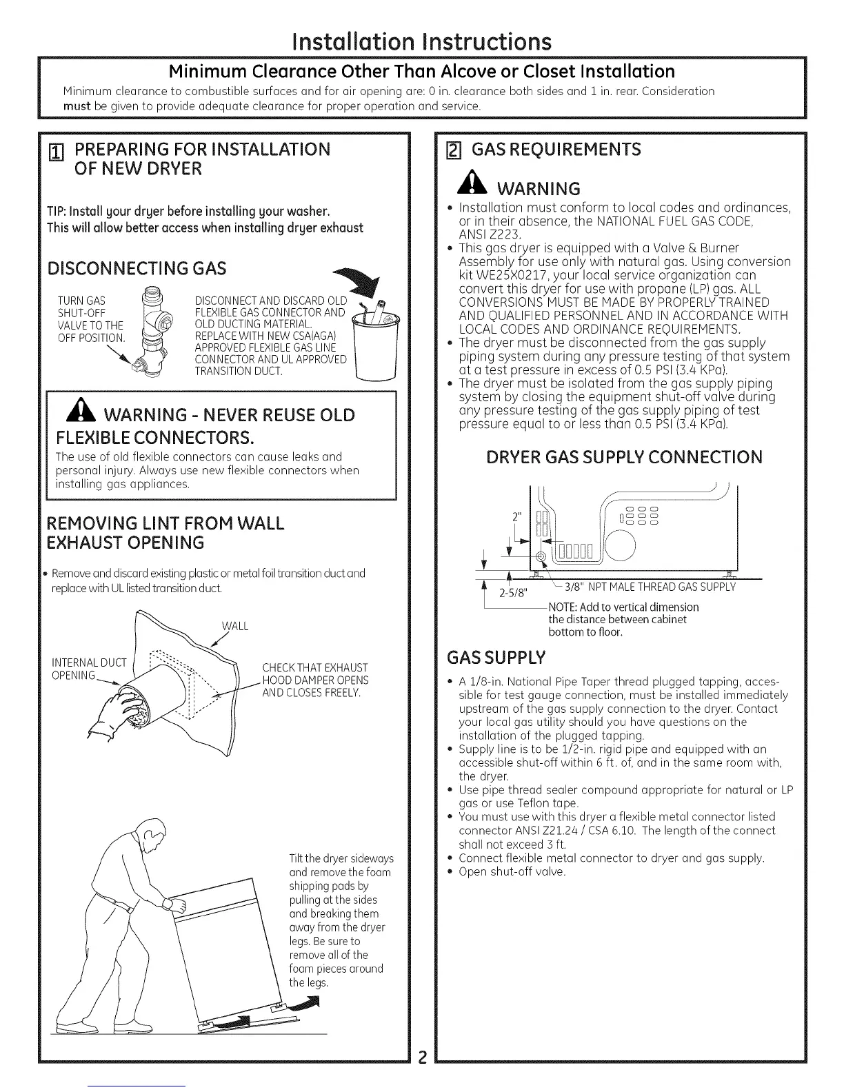
DRYER GAS SUPPLY CONNECTION
t
2-5/8"
'- 3/8" NPT MALETHREADGAS SUPPLY
NOTE: Add to vertical dimension
the distance between cabinet
bottom to floor.
GAS SUPPLY
A 1/8-in. National Pipe Taper thread plugged tapping, acces-
sible for test gauge connection, must be installed immediately
upstream of the gas supply connection to the dryen Contact
your local gas utility should you have questions on the
installation of the plugged tapping.
Supply line isto be 1/2-in. rigid pipe and equipped with an
accessible shut-off within 6 ft. of, and in the same room with,
the dryen
Use pipe thread sealer compound appropriate for natural or LP
gas or use Teflon tape.
You must use with this dryer a flexible metal connector listed
connector ANSI Z21.24 / CSA6.10. The length of the connect
shall not exceed ] ft.
Connect flexible metal connector to dryer and gas supply.
Open shut-off valve.
 Loading...