EasyManua.ls Logo

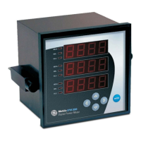
GE EPM 5300 User Manual

GE EPM 5300
100 pages
To Next Page IconTo Next Page
Page #1 background image
g
GE Industrial Systems
EPM 5200, 5300, 5350
DIGITAL MULTIFUNCTION POWER MONITORS
Instruction Manual
GEK-106557A
Copyright © 2004 GE Multilin
NORTH AMERICA EUROPE
215 Anderson Avenue, Markham, Ontario, L6E 1B3 Canada Avenida Pinoa 10 – 48710, Zamudio (Vizcaya) Spain
Tel: (905) 294-6222 Fax: (905) 201-2098 Tel: +34 94 485 88 00 Fax: +34 94 485 88 45
E-mail: info.pm@indsys.ge.com
Internet: http://www.GEindustrial.com/multilin

Table of Contents

Question and Answer IconNeed help?

Do you have a question about the GE EPM 5300 and is the answer not in the manual?

GE EPM 5300 Specifications

General IconGeneral
BrandGE
ModelEPM 5300
CategoryMeasuring Instruments
LanguageEnglish

Summary

Chapter 3: Electrical Installation

Current Circuit and CT Connection Guidelines

Guides on connecting current circuits, CT mounting, and proper polarity for accuracy.

Relay, Protection, and Pulse Output Capabilities

Discusses EPM 5300P relay features like fail-safe mode, hysteresis, and setable delays.

Chapter 4: Communication Installation

Chapter 6: Programming Overview

Chapter 8: Entering Programming Mode

Checksum Error Handling and Password Entry

Explains checksum errors, recovery, and the password entry process for programming.

Chapter 9: Programming Group 0 – Global Meter Setup

Integration Interval and Meter Address Settings

Guides on setting the integration interval and meter address for communication.

Baud Rate and Communication Settings

Details how to set the baud rate and select communication protocols.

System Configuration Switch Packs

Explains how to configure system parameters using switch packs.

Relay Mode Configuration

Explains how to set the relay mode to Fail-safe or Reset for alarm conditions.

Chapter 10: Programming Group 1 – Voltage, Amp and Watt Scale Settings

Full Scale Voltage Settings and Decimal Point Placement

Guides on setting full scale voltage, scale factor, and decimal point placement.

Chapter 11: Programming Group 2-Meter Calibration

Calibration Requirements and Warnings

Lists calibration requirements and provides crucial warnings before proceeding.

Voltage and Amperage Calibration Procedures

Details the procedures for high-end voltage and amperage calibration.

Chapter 12: Groups 4, 5 and 6—Set Limits and Relays

Trip Relay, Time Delays & Relay Mode

Explains trip relays, time delays, and relay modes for alarm and protection.

LM1/LM2 Set Limits for Voltage and Amperage (Group 4)

Details setting LM1/LM2 limits for voltage and amperage measurements.

LM1/LM2 Set Limits for Power Functions (Group 5)

Details setting LM1/LM2 limits for power functions like Kilowatt and Kilovar.

LM1/LM2 Set Limits for THD Conditions (Group 6)

Details setting LM1/LM2 limits and relay triggers for THD measurements.

Chapter 13: Phase Reversal and Phase Imbalance Set Limits/Relays

Phase Reversal and Imbalance Detection

Explains how the meter detects and alerts on phase reversal and imbalance conditions.

Voltage Phase Reversal Detection (Group 7)

Guides on configuring voltage phase reversal detection settings and relay behavior.

Percentage Voltage Phase Imbalance Settings (Group 7)

Explains how to set the percentage for voltage phase imbalance detection and relay actions.

Chapter 14: Exiting Programming Mode

Exiting Programming Mode Procedures

Details the necessary steps to exit programming mode and save changes.

Chapter 16: Ethernet Option

Ethernet Module Hardware and Status LEDs

Describes the Ethernet module hardware, RJ-45 port, and status LED functions.
Related product manuals