GEK-106310AB F650 Digital Bay Controller 5-137
5 SETTINGS 5.8 TESTING
5
5.8TESTING 5.8.1 FORCE IO–INPUT TESTING
The input testing can only be performed in relay with graphical display, see the human interfaces section in this manual for
more detailed information.
5.8.2 FORCE IO–OUTPUT TESTING
Output testing can be performed via HMI in models with graphical display and via communications through EnerVista 650
Setup in all models.
Setpoint > Inputs/Outputs > Force Outputs
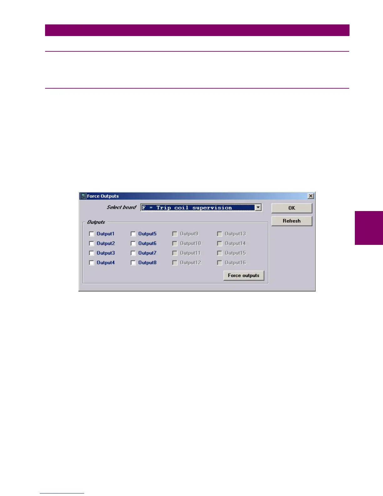
This menu allows activating each contact output in the relay, to facilitate maintenance testing. In the screen, the user can
select the I/O board to be tested, and also select which output is to be forced (operated).
After selecting the desired output, clicking on the checkbox on the left, the user must press on the Force Output button to
activate the selected output.
In order to refresh the real status of outputs, according to the information received by the relay processor, the Refresh
button must be pressed.
The following figure shows the output-testing screen:
Figure 5–43: FORCE IO

 Loading...


