❒
1
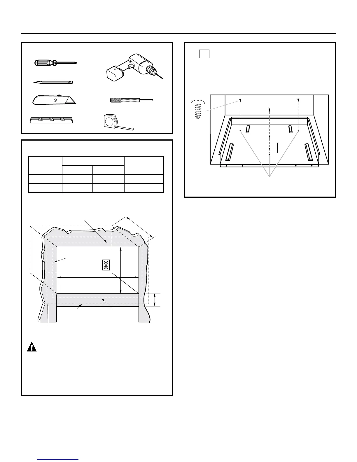
LOCATE AND INSTALL THE BASE PAN
SetBasePanintothefrontcabinetmicrowaveoven
cutoutandcenteritrightandleft.Pushbackuntilthe
frontflangeisagainstthecabinetfrontwall.Mount
theBasePanusing3screws(A).
❒ CUTOUT DIMENSIONS
WARNING — This trim kit uses air flow from the
top, bottom and sides of the trim frame. Blocking the air flow
can cause the microwave to function improperly and may
cause damage to the microwave.
Allow a 1” clearance beyond the edge of the trim frame to
provide proper air flow.
2
Installation Instructions
Min.depthwithreceptacleoutsidecutout–16
”
Min.depthwithreceptacleinsidecutout–18
”
120volt–60Hertzgroundedpowerreceptacle.
Screw A
TOOLS YOU WILL NEED
❒
2PhillipsScrewdrivers(#1)
❒
Drillwith3/32”DrillBit
❒
Centerpunch or nail
❒
Pencil
❒
Knife
❒
Level
❒
TapeMeasure
Depth
Height
5/8”Overlap
Width
7/8”Overlap
1”Clearancebeyond
trim frame
(onallsides)
3”Min.
27”models:1”overlap
30”models:2
1
/2” overlap
Bottom of trim kit must be
minimum of 36” from floor
Dimension
Trim Kit
Cutout
27” 30”
Height 16
1
/2” 16
1
/2” 15±
1
/16”
Width 26
7
/8” 29
7
/8” 24
7
/8 ±
1
/16”
BasePlan
MountingHoles
1”2.5cm;1’=0.3m
 Loading...