GE Analytical Instruments ©2006 DLM 14291 Rev. A
6-2
A I N
E N U
A N A L Y S I S C A L I B R A T I O N
C O N T R O L
E S S A G E S
A I N T E N A N C E
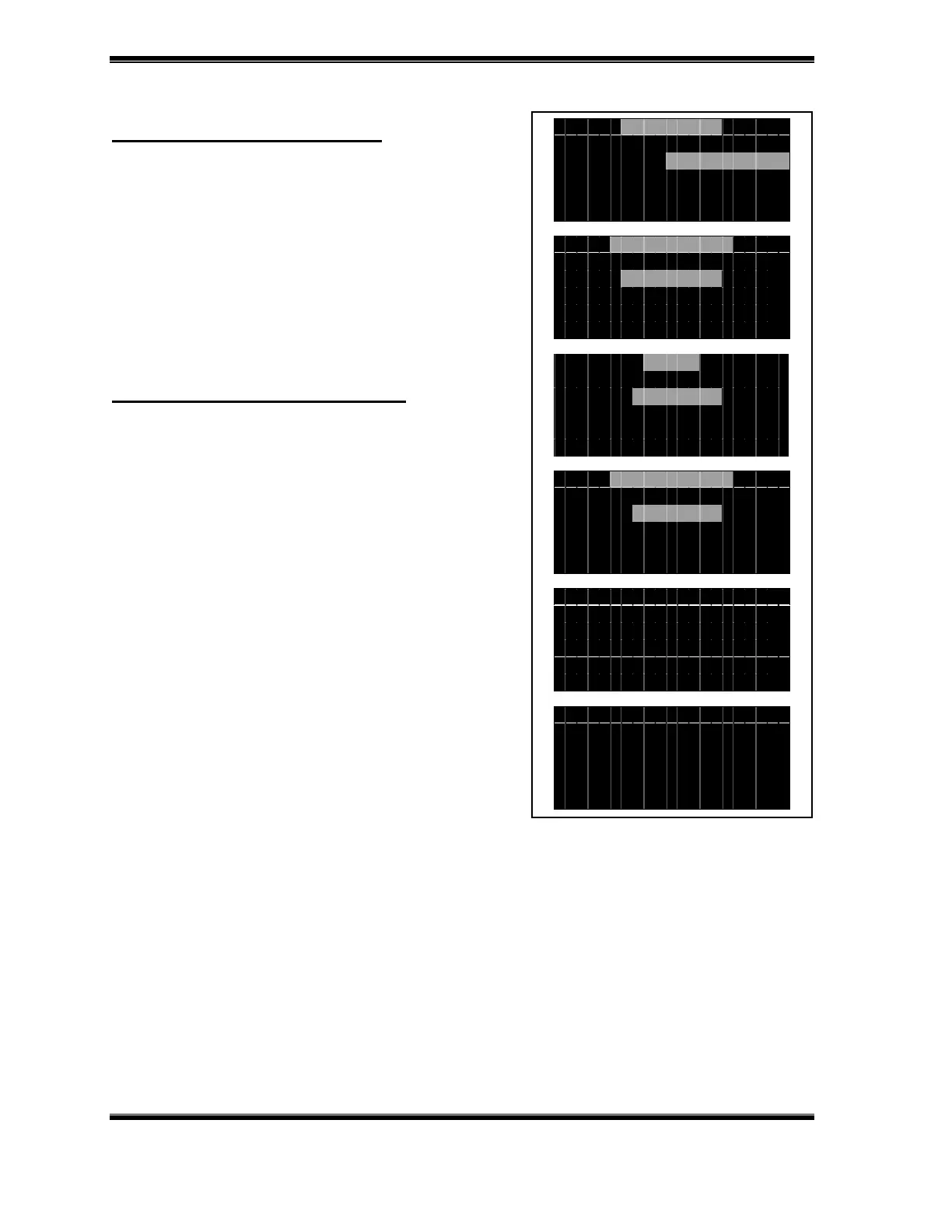
0 4 J U L 0 0 1 2 : 3 4 : 5 6
C A L I B R A T I O N
C A L I B R A T E
V I E
P R I N T
L OG I N
O P E R A T O R
S I E V E R S
C A L I B R A T I O N
Z E R O G A S
C A L I B G A S
S u p p l y g a s w i t h z e r o
N O c o n c e n t r a t i o n
E N T p r o c e e d C L R e s c
A I T t h e c a l i b r a t i o n
i s b e i n g p e r f o r m e d .
3 . 0 m V
C L R e s c a p e
Calibration with Zero Air Filter
To calibrate the zero offset using the filter,
remove the Luer plug and brass Swagelok cap
from the zero air filter. Connect the Luer
fitting on the gas sampling line directly to the
Luer adapter on the outlet of the filter and
allow the NOA to draw ambient air through the
filter for ~5 minutes.
Calibrating with Zero Air Cylinder
The setup for sampling gas from a pressurized
gas source is shown in Figure 7-1. The Luer
adapter tee included in the gas sampling
package is connected to the outlet of the
regulator on the gas cylinder, the PVC gas
sampling line connected to one leg of the tee
and the remaining leg is open to the
atmosphere. The flow rate of gas from the
pressurized source is adjusted to provide >200
mL/min with the excess gas flowing out the
open leg of the tee. Using this setup will ensure
that the calibration is performed at the same
flow rate as the measurements. Allow the NOA
to sample the zero air for ~ 5 minutes.
To calibrate of offset:
• Start the NOA and from the Measurement Menu, press CLEAR to switch to the
Main Menu.
• Use the arrow buttons to scroll to Calibration and press ENTER.
• The Calibration Menu is displayed with three options: Calibrate, View and
Print.
• Select Calibrate to display the Login menu.
 Loading...


