Ibias /Inom
I
diff/Inom
Is1
Is-CTS
I
s-HS1
Is-HS2
Is2
K
1
K2
Restraint region
O
perate region
V03127
TC and CT errors
Figure 44: Effect of CTS restrain
3.8.8 CIRCUITRY FAIL ALARM
Under normal operating conditions there should be no differential current (although there might be a small
amount due to CT mismatch). Under conditions such as curr
ent transformer (CT) failure or a failure of the CT
circuitry, a small differential current may be seen. This product can monitor the scheme for such conditions with a
dual slope differential characteristic, by enabling the Circuitry Fail setting in the DIFF PROTECTION column. The
characteristic is then defined by the settings Is-cctfail and k-cctfail. By default it is a time-delayed element to
prevent conflict with the tripping characteristic in the event of a genuine transformer fault. But if the ratio of
differential to bias current exceeds the Is-cctfail and k-cctfail settings, but does not exceed the Is1 and k1
settings, for the duration of the Is-cctfail setting, a circuitry fail alarm is raised. The Is-cctfail delay is set to 5
seconds by default.
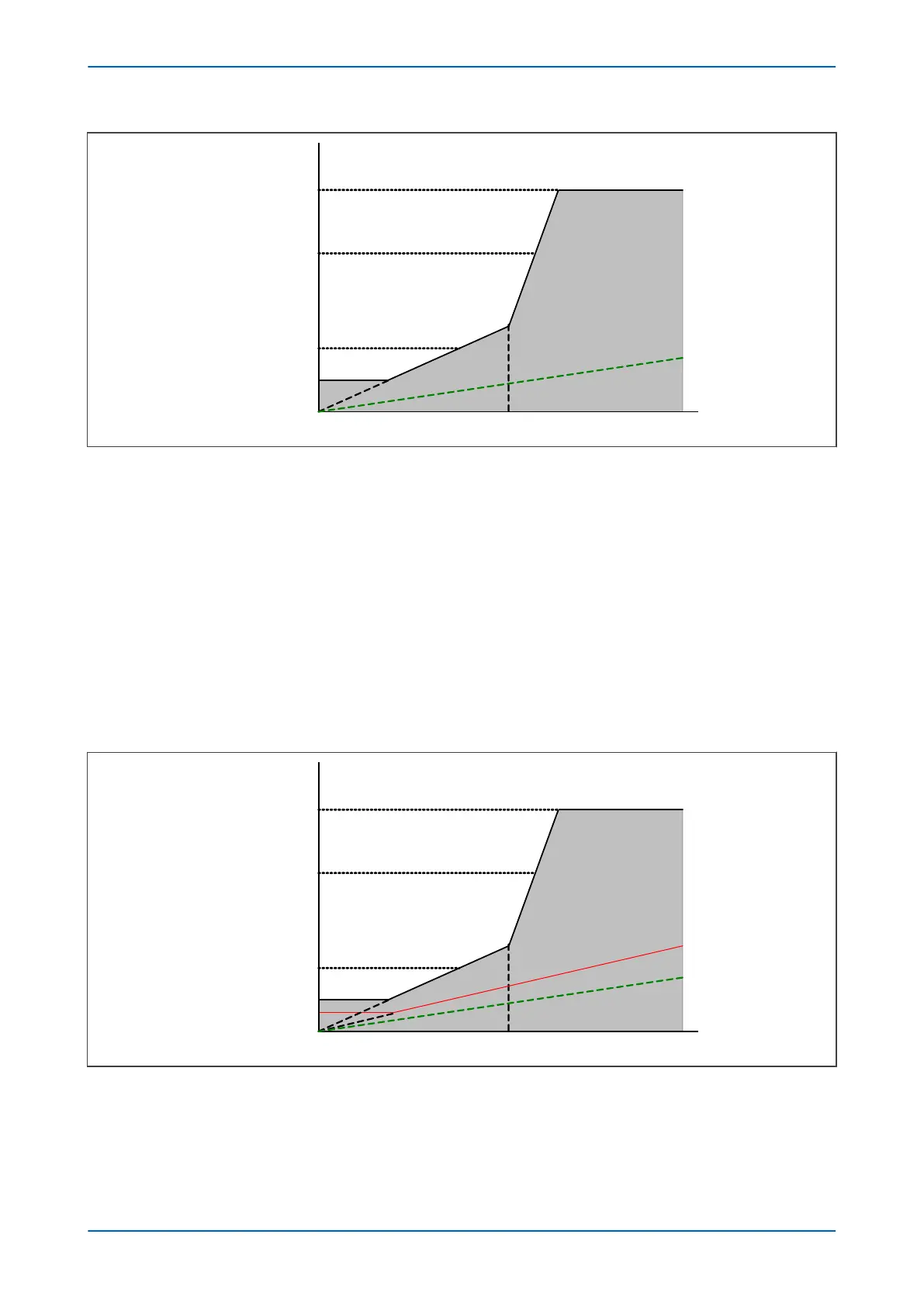
The level at which the circuitry fail alarm would operate under these circumstances is shown by the red line as
follows:
Ibias /Inom
I
diff/Inom
Is-cctfail
Is1
Is-CTS
I
s-HS1
Is-HS2
Is2
K
1
K2
K-cctfail
Restraint region
O
perate region
V03128
TC and CT errors
Figure 45: Bias characteristic with circuitry fail alarm
P64x Chapter 6 - Transformer Differential Protection
P64x-TM-EN-1.3 115

 Loading...


