Bk 1 Bk 3Bk 2
T1 CT
400 :5
T2 CT
400:5
T3 CT
1000 :1
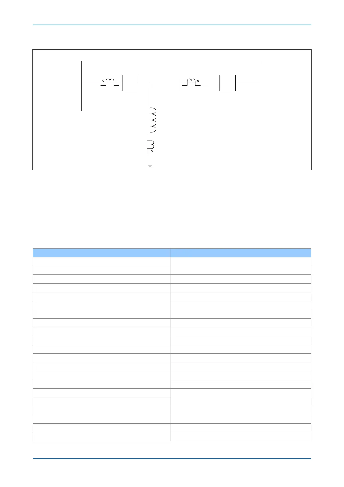
500 kV
163 .3 MVA
Busbar A
Busbar B
V03121
Figure 58: Shunt Reactor single line diagram
The bias differ
ential element in the P643 would be used to protect the reactor. In a reactor application the low set
differential element Is1, should be set between 10%-15%. Inrush current in a shunt reactor does not appear as a
differential current like that which appears in a transformer, unless the CT saturates after some time due to long
DC time constant. Though the level of second harmonic in many cases can be relatively high there are many cases
with no or very low content of harmonics. Since the level of 2nd harmonic is small in shunt reactors compared with
transformers, the second harmonic blocking can be set as low as 10% to enhance stability during energization.
The high set 1 differential element, Is-HS1, can be set to 250% of the reactor current at rated voltage.
Set the following parameters in the SYSTEM CONFIG column:
Setting in GROUP 1 SYSTEM CONFIG Value
Winding Config HV+LV
Winding Type Conventional
HV CT Terminals 011
LV CT Terminals 100
Ref Power S 163.3 MVA
Ref Vector Group 0
HV Connection Y-Wye
HV Grounding Ungrounded
HV Nominal 500.0 kV
HV Rating 163.3 MVA
% Reactance 40.00%
LV Vector Group 0
LV Connection Y-Wye
LV Grounding Ungrounded
LV Nominal 115.0 kV
LV rating 163.3 MVA
Phase Sequence Standard ABC
VT Reversal No Swap
CT1 Reversal No Swap
CT2 Reversal No Swap
CT3 Reversal No Swap
Chapter 6 - Transformer Differential Protection P64x
134 P64x-TM-EN-1.3

 Loading...


