2
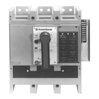
Figure 1. Old terminal board mounted on the breaker (2500–4000 A
shown).
7. Push in the locking lever on the side of the trip unit
mounting plate and carefully lift off the trip unit.
8. Remove the trip unit mounting plate as follows for
the appropriate breaker frame size:
• 800–2000 A: Remove the two mounting screws on
the trip unit plate and loosen the
1
/4-20 screw on
the side of the assembly, as shown in
Figure 2.
Remove the trip unit mounting plate assembly.
• 2500–4000 A: Remove the two screws securing the
trip unit mounting plate to the center-phase sensor
shell, as shown in
Figure 3. Lift off the trip unit
mounting plate. Take care that the two nuts in the
slots in the top of the CT don’t fall out.
9. Use pliers to bend the two locking tabs that secure
the large plug to the trip unit mounting plate, as
shown in
Figure 4. Slide the plug off the mounting
plate, then remove and save the plug mounting
bracket.
10. Connect the leads from the new terminal board [1]
to the large plug, as shown in
Figure 5, according to
the wiring diagram in
Figure 6. Use AMP tool
455822-2 to remove incorrectly placed pins from the
plug.
Figure 2. Trip unit mounting plate on an 800–2000 A breaker.
Figure 3. Trip unit mounting plate on a 2500–4000 A breaker.
Figure 4. Bending the locking tabs to remove the large plug from the
trip unit mounting plate.
Figure 5. Connecting the leads from the new terminal board to the trip
unit plug.
4-20
Mounting
Screw
Mounting
Screws
Mounting
Screws
 Loading...