© 2016 General Electric All Rights Reserved
2
Figure 2: Install Retainer to secure breaker
See figure 3, load center fully assembled with kit
Figure 3: shows Kit fully assembled
5. Remove the backing from the enclosed "SERVICE
DISCONNECT" label and attach it to the dead
front/shield besides the main circuit breaker opening.
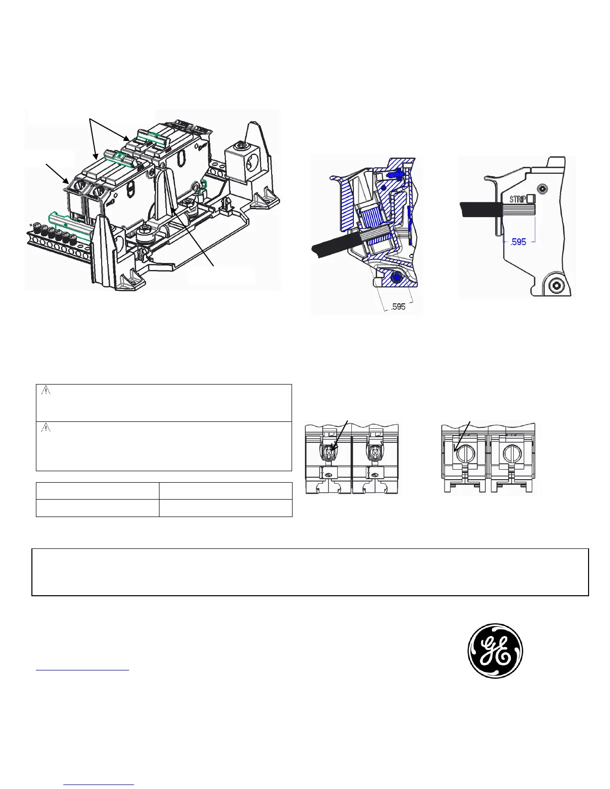
WARNING: Service barriers (A) must be correctly
installed on the line side of a main device in GE load
centers, and MSLC to ensure isolation from live parts.
WARNING: Installing an incorrect size wire than the
specified sizes for each circuit breaker frame will negate
the barrier ability to protect personnel from exposed live
components.
Table 1: Shows the allowable wire range for the barrier.
The wires must be stripped to the correct length to maintain
isolation. Strip the wire to a maximum of 0.595 inches.
After stripping the wires to the required length, the wires can
be installed as shown in Figure 4. The service barrier must be
correctly installed to maintain electrical isolation from
accidental contact. Torque the wires according the torque
specification on the breaker.
Figure 4: Stripped wire installed
The strip wire length are measured to the scale provided on
side of main circuit breaker, as shown on Figure 5.
Some THQL (1p and 2p up to 60 Amps) are finger safe and do
not require a Service barrier. See Figure 6.
Barriers not required Barriers required
Figure 6: Breakers Where Service Barriers Are Required
Imagination at work
GE Configured Solutions
41 Woodford Ave.
Plainville, CT 06062
www.geindustrial.com
To contact GE Industrial Solutions post sales service team, call 888-437-3765
*INDICATES A TRADEMARK OF THE GENERAL ELECTRIC COMPANY AND/OR ITS SUBSIDIARIES.
INFORMATION PROVIDED IS SUBJECT TO CHANGE WITHOUT NOTICE. PLEASE VERIFY ALL DETAILS WITH GE. ALL VALUES ARE DESIGN OR TYPICAL WHEN MEASURED UNDER LABORATORY CONDITIONS, AND GE MAKES
NO WARRANTY OR GUARANTEE, EXPRESS OR IMPLIED, THAT SUCH PERFORMANCE WILL BE OBTAINED UNDER END-USE CONDITIONS
These instructions do not purport to cover all details or variations in equipment nor do they provide for every possible
contingency that may be met in connection with installation, operation, or maintenance. Should further information be desired
or should particular problems arise that are not covered sufficiently for the purchaser’s purposes, the matter should be
referred to the GE Company.
 Loading...