FAILURE CODESSERVICE MODE
Service Mode can be entered by the following steps:
1. Press and Hold the Front Right Burner ON/OFF key for 7 seconds
until tone is heard and “1” appears on the timer.
2. Press and Hold Rear Right Burner ON/OFF key for 7 seconds
until tone is heard and Software version appears on the timer.
SEt – SETTING UP SERVICE REPLACEMENT CONTROLS
Service Replacement UIs must be set up with the appropriate
model number to function correctly.
1. After replacing the control, power up the unit.
2. Upon power up the UI will display the letter SEt after a few
VHFRQGV2QWKH*(8,XQLWVDOOWKH/('VPD\WXUQRQ¿UVWIRUXS
to 10 seconds before SEt appears on screen.)
3. Using the Timer up and down keys select the correct model
QXPEHUEDVHGRȺWKHWDEOHEHORZ
4. Press and Hold the Timer Select (or Timer Start on models where
this key is available) for 7 seconds to store this model number in
the control.
5. The control should restart and operate normally.
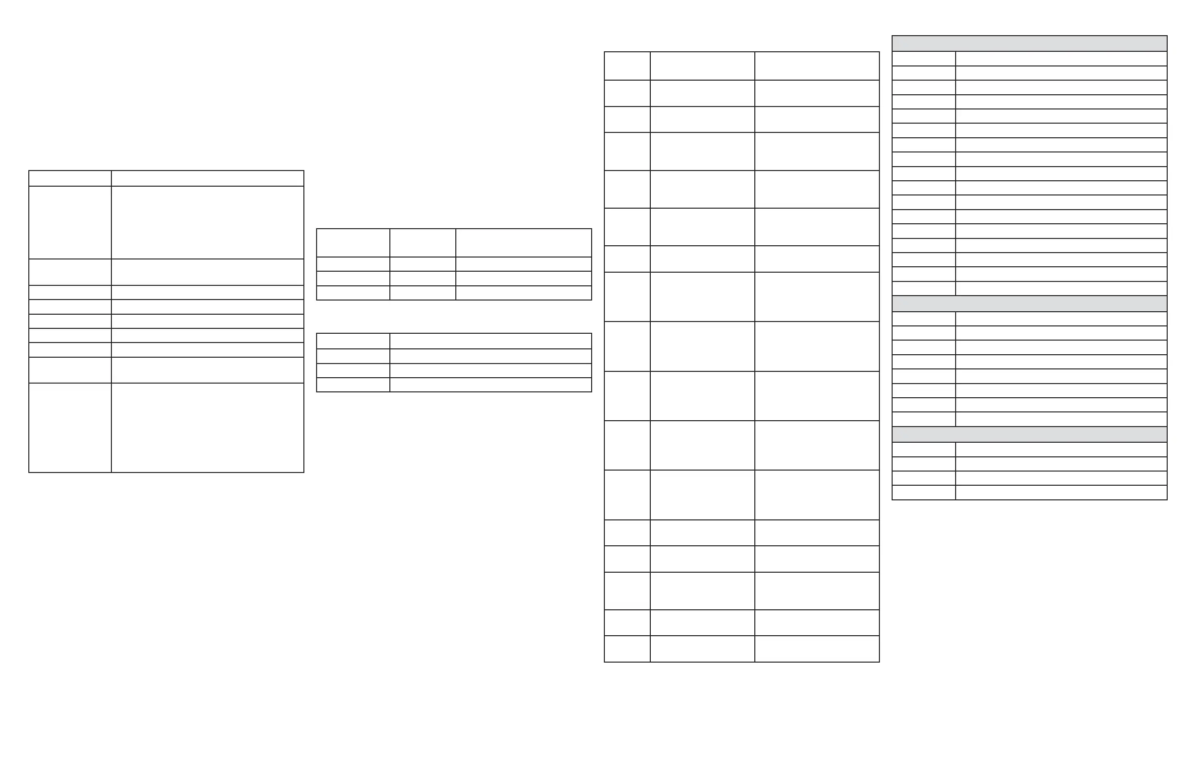
DIAGNOSTICS MODE SUMMARY
MODEL SELECTIONS FOR 36” INDUCTION
The Table below describes what key provides what diagnostic
features each key will do.
Key Response
Left Rear + Displays failure codes on the Timer. Pressing
this key multiple times will cycle through
each failure code until dashes appear
showing the end of the codes. If no active
failures exist only dashes will be shown with
each press.
$OO2Ⱥ Pressing and holding for 5 seconds will clear
the Failure Code that is currently displayed.
Left Front + Turns on all the LEDs for 5 seconds.
Left Front - Exit Service Mode.
Right Front - Display main board software version
Right Front + Display Induction board #1 software version
Right Rear - Display Induction board #2 software version.
Right Rear + Display Induction board #3 software version
(On 30” unit, this key is not valid).
Timer Select
(or Timer ON/OFF)
ONLY use this when a mistake has been
made in setting the model number for a
service replacement board.
To clear the service model number, press and
hold for 7 seconds. Control will show SEt in
timer block, ready to reprogram the service
control’s model number.
Service
Model Index Model Description
AA2 CHP9536xxxx 36” Induction Café Blue
AF2 ZHU36Rxxxx 36” Induction Monogram White
C2 PHP9036xxxx µ,QGXFWLRQ3UR¿OH
User Interface
J1 Pin1 7.5V DC Power
J1 Pin2 GE Communication Bus
J1 Pin3 NC
J1 Pin4 Heating Enable. +5VDC Active
J1 Pin5 NC
J1 Pin6 NC
J1 Pin7 NC
J1 Pin8 Logic Ground
J6 Pin1 Service 7.5V DC Power
J6 Pin2 Service Communication Bus
J6 Pin3 Service Logic Ground
J4 Pin1 Fan 2 Speed Detection
J4 Pin2 Fan 1 Speed Detection
J4 Pin3 Fan 2 Low Speed. +5VDC Active
J4 Pin4 Fan 2 High Speed. +5VDC Active
J4 Pin5 Fan 1 Low Speed. +5VDC Active
J4 Pin6 Fan 1 High Speed. +5VDC Active
Induction Tray – Filter Board
J8 Pin1 Logic Ground
J8 Pin2 Heating Enable. +5VDC Active
J8 Pin3 Fan Speed Detection
J8 Pin4 12V DC Power
J8 Pin5 7.5V DC Power
J8 Pin6 Fan High Speed. +5VDC Active
J8 Pin7 Fan Low Speed. +5VDC Active
J8 Pin8 NC
Induction Tray – Generator Board
J501 Pin1 7.5V DC Power
J501 Pin2 Communication Bus
J501 Pin3 Logic Ground
J502 Pin1~4 Model Selector Plug
Fault
Code Issue Description Possible Fixes
SEt Model number not
programmed into UI
Program model number via
service tools.
F10~F11 Problem with LED’s on
user interface
Check Power. Replace UI
Board.
F61 Cannot communicate
with induction module
that powers left coils
Check wires connecting UI
to induction Tray. Replace
UI. Replace induction Tray.
F62 Cannot communicate
with Induction Module
that powers right coils
Check wires connecting UI
to induction Tray. Replace
UI. Replace induction Tray.
F63 Cannot communicate
with induction module
that powers right coils
Check wires connecting UI
to induction Tray. Replace
UI. Replace induction Tray.
F70~F76 User Interface key error Clean UI. Cycle power.
Replace UI Board.
FA0 Fan Harness(is) not
connected
Check wires connecting UI
to Induction Tray. Check
Fan, UI and induction Tray.
Replace fan.
FA1 Fan1 is not running at
the correct Low speed
Check wires connecting UI
to Induction Tray. Check
Fan, UI and induction Tray.
Replace fan.
FA2 Fan1 is not running at
the correct High speed
Check wires connecting UI
to Induction Tray. Check
Fan, UI and induction Tray.
Replace fan.
FA3 Fan2 is not running at
the correct Low speed
Check wires connecting UI
to Induction Tray. Check
Fan, UI and induction Tray.
Replace fan.
FA4 Fan2 is not running at
the correct High speed
Check wires connecting UI
to Induction Tray. Check
Fan, UI and induction Tray.
Replace fan.
FA5, FA9,
FAA
Bad coil thermistor
reading
Check coil thermistor and
induction Tray. Replace coil.
FA6 Low or high line voltage Check line voltage. Replace
Induction Tray.
FA7 Missing line frequency Check line voltage/
frequency. Replace
Induction Tray.
FA8, FAB Bad induction driver
(IGBT)
Replace Induction Tray.
FAC Induction
microprocessor error
Replace Induction Tray.
THERMISTOR RESISTANCE READINGS
Degrees F Thermistor Resistance (approximate)
72° F Nű
150° F Nű
518° F ű
RJ-45 is a service jack provided for GE technicians to use on the
front left bottom corner of the unit.
MODEL NUMBER
PHP9036
IMPORTANT
SERVICE INFORMATION
DO NOT DISCARD
Pub No. 31-17142 10-14 GE
 Loading...