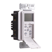
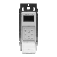
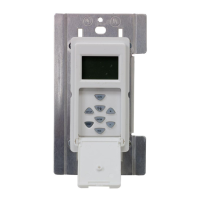
In-wall
SunSmart
™
Digital Timer
Installing the timer on the LOAD Side
1. Using the Load Side of Figure 3 as a visual reference, remove the LOAD Side 3-way
switch and the four wires, labeling the wire removed from the common terminal as
LOAD (4) and the wires from the HOT terminals (H) as Traveler-1 (5) and Traveler-2 (7).
2. Using the Timer On LOAD Side of Figure 4 as a visual reference for the remaining
steps, connect the LOAD wire (4) to the LOAD terminal of the timer.
3. Connect the Traveler-2 wire (7) to LINE terminal of the timer.
4. Connect the Traveler-1 wire (5) to the TRAVELER terminal of the timer.
5. Connect the white Neutral wire (2) from the switch box to the NEUTRAL terminal of
the timer. More neutral wires may be bundled in the back of the switch box; there
may be several neutral wires bound together with a wire nut. Add the Neutral wire
to the other neutral wires bound together, ensuring the wire nut is tight. If needed
use included jumper.
6. Connect the green Ground wire (3) in the switch box to the GROUND terminal of
the timer.
7. Carefully tuck the wires into the switch box, leaving room for the timer.
8. Use the supplied screws to install the timer, being careful not to crush or pinch the
wires.
9. Restore power at the circuit breaker or fuse box.
10. Verify that the LOAD turns ON/OFF when you manually turn the timer ON and
OFF. Perform this test with the remote switch in both positions. You should hear
the timer relay click ON/OFF. If you hear the relay click but the LOAD does not turn
ON/OFF properly, check your wiring.
11. If the load does not operate properly, disconnect the power at the circuit breaker or
fuse box. Then swap the Traveler-2 (Line) wire (7) and Traveler-1 wire (5) on the timer.
Timer on the LINE side 3-way installation instructions
NOTE: If you are unsure or unclear about this installation or if the wires in your box do
not match the manual (not all switch boxes have neutral wires), contact a qualified,
licensed electrician.
Preparing the switch on the LOAD side
1. Disconnect the power from the circuit by turning off the circuit breaker or removing
the fuse from the fuse box.
2. Using the Switch On LOAD Side of Figure 5 as a visual reference, label and remove
the LOAD wire (4) from the common terminal (C) and the Traveler-2 wire (7) from the
HOT terminal (H).
3. Using Figure 6 as a visual reference, connect the jumper wire (6) (supplied), the LOAD
wire (4) from the common terminal (C), and the Traveler-2 wire (7) together. You
should have three wires connected with one wire nut. If needed use the included
jumper.
4. Connect the other end of the jumper wire (6) back to the common terminal (C) on
the switch. Consider recording the marking/color coding of the Traveler-1 (5) and
Traveler-2 (7) wires so you can tell them apart for later use.
5. Carefully tuck the wires into the switch box leaving room for the timer.
6. Install the switch back into the box.
Installing the timer on the LINE side
1. Using the LINE Side of Figure 5 as a visual reference, remove the LINE Side 3-way
switch and the four wires, labeling the wire removed from the common terminal
(C) as LINE (1) and the wires from the HOT terminals (H) as Traveler-1 (5) and
Traveler-2 (7).
2. Using the Timer on LINE Side of Figure 6 as a visual reference for the remaining
steps, connect the LINE wire (1) to the LINE terminal of the timer.
3. Connect the white Neutral wire (2) to the NEUTRAL terminal of the timer. More
neutral wires may be bundled together in the back of the switch box; there may be
several neutral wires bound together with a wire nut. Add the Neutral wire to the
other neutral wires bound together, ensuring the wire nut is tight.
4. Connect the Traveler-1 wire (5) to the TRAVELER terminal of the timer and the
Traveler-2 wire (7) to the LOAD terminal of the timer.
5. Connect the green Ground wire (3) to the GROUND terminal of the timer.
6. Carefully tuck the wires into the switch box, leaving room for the timer.
7. Use the supplied screws to install the timer, being careful not to crush or pinch the
wires.
8. Restore power at the circuit breaker or fuse box.
9. Verify that theLOAD turns ON/OFF when you manually turn the timer ON and OFF.
Perform this test with the remote switch in both positions. You should hear the timer
relay click ON/OFF. If you hear the relay click but the LOAD does not turn ON/OFF
properly, check your wiring.
10. If the load does not operate properly, disconnect the power at the circuit breaker or
fuse box. Then swap the Traveler-2 (LOAD) wire (7) and Traveler-1 wire (5) at the timer
or the toggle switch.
TRAVELER
LOADLINE
NEUTRAL
Typical Wiring Diagram for a 3-way installation
with timer on line side
Figure 6 - Connecting the timer wires for a 3-way
installation - timer on line side
1 = Line
2 = Neutral
3 = Ground
4 = Load
5 = Traveler-1
6 = Jumper
*7 = Traveler-2
C = Common
terminal
2
7
5
6
3
Ground
SWITCH ON LOAD SIDE
4
Load
C
Figure 5 - Typical wiring
schematic for 3-way installation
5
1
7
Hot Side
Line
LINE SIDE LOAD SIDE
C
H H
5
4
7
C
H H
Load
In a typical 3-way application there are two 3-way switches. The switch on the
“HOT” side has the common terminal tied to 120VAC. The switch on the “LOAD”
side has the common terminal tied to the load that the switches turn off and on.
Line
Neutral
Traveler-2 (Load)
Ground
Traveler-1
5
3
7
1
2
TIMER ON LINE SIDE
3
3
Ground
*Traveler-2 (7) carries Load
to the timer
H H
Changing the faceplate
This device includes a light almond faceplate. To switch
faceplates, proceed as follows:
1. Gently remove the white faceplate using a flat head
screwdriver. Find the slots at the bottom left or right of
the white faceplate and pry the faceplate loose (see
Figure 1). Work around the faceplate until it pops off.
2. Find the light almond faceplate in the package. Place
the new faceplate into position and carefully push the
bottom of the faceplacte until it snaps into place.
Single-pole Installation
NOTE: If you are unsure or unclear about this installation or if the wires in your box do
not match the manual (not all switch boxes have neutral wires), contact a qualified,
licensed electrician.
Installation instructions (single-pole)
1. Turn OFF the main power at the circuit breaker or fuse box.
2. Remove the existing switch.
3. Connect the timer to the wall box wires as shown in Figure 2.
a) Connect the hot/live LINE wire to the LINE terminal of the timer.
b) Connect the hot/live LOAD wire to the LOAD terminal of the timer.
c) Connect the Ground wire to the GROUND terminal of the timer.
d) Connect the Neutral wire to the NEUTRAL terminal of the timer. Often the Neutral
wire can be found in the back of the wire box connected with a wire nut. There may
be several neutral wires bound together. Add the timer Neutral wire to the other
neutral wires, bound together making sure the wire nut is tight. If needed use the
included jumper.
4. Ensure that all terminals are tightened to between 8.85 and 12.39 lbf-in., and tuck the
wires into the wall box, leaving room for the timer.
5. Use the screws to mount the timer to the wall box, being careful not to crush any
wires.
6. Reinstall your wallplate.
7. Turn the main power on at the circuit breaker.
8. If the timer does not turn on, disconnect the power at the circuit breaker or fuse box.
Swap the LINE and LOAD wires on the timer. Remount the timer and wallplate, then
restore power at the fuse box or circuit breaker.
Timer on LOAD side 3-way installation instructions
NOTE: If you are unsure or unclear about this installation or if the wires in your box do
not match the manual (not all switch boxes have neutral wires), contact a qualified,
licensed electrician.
Preparing the switch on the LINE Side
1. Disconnect the power from the circuit by turning off the circuit breaker or removing
the fuse from the fuse box.
2. Using the LINE Side of Figure 3 as a visual reference, label and remove the LINE wire
(1) from the common terminal (C) and the Traveler-2 wire (7) from the HOT terminal (H).
3. Using Figure 4 as a visual reference, connect the jumper wire (6) (supplied), the LINE
wire (1) from the common terminal (C), and the Traveler-2 wire (7) together. You should
have three wires connected with one wire nut.
4. Connect the other end of the jumper wire (6) back to the common terminal (C) on
the switch. Consider recording the marking/color coding of the Traveler-1 (5) and
Traveler-2 (7) wires so you can tell them apart for later use.
5. Carefully tuck the wires into the box, leaving room for the switch.
6. Install the switch back into the box.
TRAVELER
LOADLINE
NEUTRAL
Figure 3 - Typical wiring
schematic for 3-way installation
2
7
5
6
1
3
Ground
C
Typical Wiring Diagram for 3-way installation
with timer on load side
Load
Line
5
1
7
3
3
Hot Side
Line
Ground
LINE SIDE
SWITCH ON LINE SIDE
LOAD SIDE
TIMER ON LOAD SIDE
C
H H
5
4
7
C
H H
Figure 4 - Connecting the timer wires for a
3-way installation - timer on load side
Load
1 = Line
2 = Neutral
3 = Ground
4 = Load
5 = Traveler-1
6 = Jumper
*7 = Traveler-2
C = Common
terminal
In a typical 3-way application there are two 3-way switches. The switch on the
“HOT” side has the common terminal tied to 120VAC. The switch on the “LOAD”
side has the common terminal tied to the load that the switches turn on and off.
Load
Neutral
Traveler-2 (Line)
Ground
Traveler-1
5
3
7
4
2
*Traveler-2 (7) carries Line to the timer
H H
Installation
Instructions
Figure 1 - Removing the faceplate
TIMER
WALL BOX
Line
TRAVELER
LOADLINE
NEUTRAL
Included Neutral Jumper
Load
Ground
Figure 2 - Connecting the timer wires for single-pole installation
5/8” (1.6cm)
Wire Strip Length
WIRE
Step-by-Step
Instructional Video
RISK OF ELECTRIC SHOCK
• SHUT OFF POWER AT FUSE BOX OR
CIRCUIT BREAKER BEFORE INSTALLATION
• DO NOT USE IN WET LOCATIONS
• USE INDOORS ONLY
WARNING
RISK OF FIRE
•DO NOT USE TO CONTROL APPLIANCES THAT CONTAIN HEATING
ELEMENTS (COOKING APPLIANCES, HEATERS, IRONS, ETC.)
• DO NOT EXCEED ELECTRICAL RATINGS
• DO NOT USE TO CONTROL RECEPTACLES
• USE COPPER WIRE ONLY WITH THIS DEVICE
• TIGHTEN ALL CONNECTIONS TO 1-1.4 N-m (8.85 TO 12.39 LBF-IN.)
• FOR SUPPLY CONNECTIONS, USE 14 AWG OR LARGER WIRE
RATED AT LEAST 75°C.
• FOR GROUNDING LEAD, USE 12 AWG OR LARGER WIRE RATED
AT LEAST 75°C.