5-214 T60 Transformer Protection System GE Multilin
5.6 GROUPED ELEMENTS 5 SETTINGS
5
b) PERCENT DIFFERENTIAL
PATH: SETTINGS GROUPED ELEMENTS SETTING GROUP 1(6) TRANSFORMER PERCENT DIFFERENTIAL
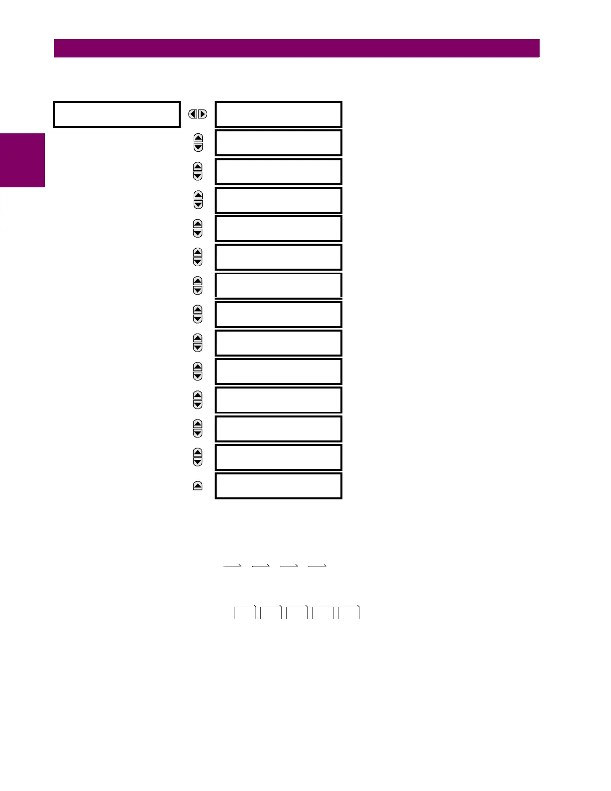
The calculation of differential (I
d
) and restraint (I
r
) currents for the purposes of the percent differential element is described
by the following block diagram, where “” has as its output the vector sum of inputs, and “max” has as its output the input of
maximum magnitude; these calculations are performed for each phase.
The differential current is calculated as a vector sum of currents from all windings after magnitude and angle compensation.
(EQ 5.27)
The restraint current is calculated as a maximum of the same internally compensated currents.
(EQ 5.28)
The element operates if I
d
> PKP and I
d
/ I
r
> K, where PKP represents a percent differential pickup setting and K is a
restraint factor defined by the relays settings Slope 1, Slope 2, and a transition area between breakpoint 1 and breakpoint 2
settings.
PERCENT
DIFFERENTIAL
PERCENT DIFFERENTIAL
FUNCTION: Disabled
Range: Disabled, Enabled
MESSAGE
PERCENT DIFFERENTIAL
PICKUP: 0.100 pu
Range: 0.050 to 1.000 pu in steps of 0.001
MESSAGE
PERCENT DIFFERENTIAL
SLOPE 1: 25%
Range: 15 to 100% in steps of 1
MESSAGE
PERCENT DIFFERENTIAL
BREAK 1: 2.000 pu
Range: 1.000 to 2.000 pu in steps of 0.001
MESSAGE
PERCENT DIFFERENTIAL
BREAK 2: 8.000 pu
Range: 2.000 to 30.000 pu in steps of 0.001
MESSAGE
PERCENT DIFFERENTIAL
SLOPE 2: 100%
Range: 50 to 100% in steps of 1
MESSAGE
INRUSH INHIBIT
FUNCTION: Adapt. 2nd
Range: Disabled, Adapt. 2nd, Trad. 2nd
MESSAGE
INRUSH INHIBIT
MODE: Per phase
Range: Per phase, 2-out-of-3, Average
MESSAGE
INRUSH INHIBIT
LEVEL: 20.0% fo
Range: 1.0 to 40.0% of f
0
in steps of 0.1
MESSAGE
OVEREXCITN INHIBIT
FUNCTION: Disabled
Range: Disabled, 5th
MESSAGE
OVEREXCITN INHIBIT
LEVEL: 10.0% fo
Range: 1.0 to 40.0% of f
0
in steps of 0.1
MESSAGE
PERCENT DIFF BLOCK:
Off
Range: FlexLogic operand
MESSAGE
PERCENT DIFFERENTIAL
TARGET: Self-reset
Range: Self-reset, Latched, Disabled
MESSAGE
PERCENT DIFFERENTIAL
EVENTS: Disabled
Range: Disabled, Enabled
I
d
I
1
comp
I
2
comp
I
3
comp
I
4
comp
I
5
comp
++++=
I
r
max I
1
comp
I
2
comp
I
3
comp
I
4
comp
I
5
comp
,,,(, )=

 Loading...


