GE Multilin T60 Transformer Protection System 8-5
8 COMMISSIONING 8.2 DIFFERENTIAL CHARACTERISTIC TEST EXAMPLES
8
b) TEST FOR ZERO DIFFERENTIAL CURRENT
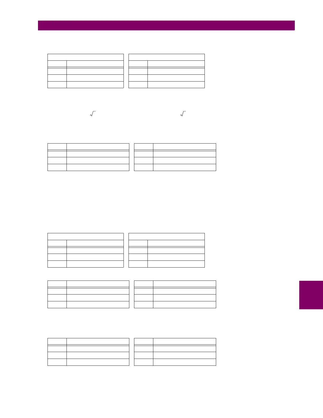
1. Inject the following currents into the relay:
2. These are determined as follows:
(EQ 8.7)
From the Current Distribution diagram above, there is a secondary current for HV
phases B and C, and a secondary current for LV phases b and c.
3. The relay should display the following differential and restraint currents and the element should not operate:
c) MINIMUM PICKUP TEST
Reduce the restraint current I
r
to a value lower than 0.67 pu (the restraint corresponding to the intersection of Slope 1 and
the pickup). This is obtained from , where 0.1 is the differential setting of minimum pickup, and
0.15 is the setting of Slope 1. Note that
(EQ 8.8)
where I
ri
is an intersection of Minimum PKP and Slope 1 calculated as PKP/Slope 1 value.
4. Change the current magnitude as follows:
5. The following differential and restraint current should be read from the T60 actual values menu:
The relay will not operate since I
d
is still lower that the 0.1 pu MINIMUM PICKUP setting.
6. Increase I
1
to 0.2 A. The differential current increases to and .
7. Verify that the Percent Differential element operates and the following are displayed in the actual values menu:
WINDING 1 WINDING 2
PHASE SINGLE CURRENT (I
1
) PHASE SINGLE CURRENT (I
2
)
A0 A 0° A 0 A 0°
B 0.434 A 0° B 0.8 A –180°
C 0.434 A –180° C 0.8 A 0°
PHASE DIFFERENTIAL CURRENT (I
d
) PHASE RESTRAINT CURRENT (I
r
)
A0 0° A 0 0°
B0 0° B 0.801 pu –180°
C0 0° C 0.801 pu 0°
WINDING 1 WINDING 2
PHASE SINGLE CURRENT (I
1
) PHASE SINGLE CURRENT (I
2
)
A0 A 0° A 0 A 0°
B 0.15 A 0° B 0.23 A –180°
C 0.15 A –180° C 0.23 A 0°
PHASE DIFFERENTIAL CURRENT (I
d
) PHASE RESTRAINT CURRENT (I
r
)
A0 0° A 0 0°
B 0.044 pu 0° B 0.275 pu –180°
C 0.044 pu 0° C 0.275 pu 0°
PHASE DIFFERENTIAL CURRENT (I
d
) PHASE RESTRAINT CURRENT (I
r
)
A0 0° A 0 0°
B 0.136 0° B 0.367 pu –180°
C 0.136 0° C 0.367 pu 0°
I
n
w
1
20 10
6
VA
311510
3
V
---------------------------------------------
100.4 A, I
n
w
2
20 10
6
VA
3 12.47 10
3
V
--------------------------------------------------
925.98 A== = =
0.866 pu 100.4 A 200 0.434 A=
0.866 pu 925.98 A 1000 0.8 A=

 Loading...