9-4 L60 Line Phase Comparison System GE Multilin
9.2 DISTANCE BACKUP/SUPERVISION 9 APPLICATION OF SETTINGS
9
9.2DISTANCE BACKUP/SUPERVISION 9.2.1 DESCRIPTION
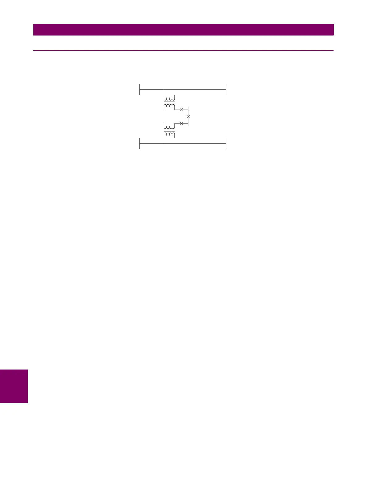
Many high voltage lines have transformers tapped to the line serving as an economic approach to the supply of customer
load. A typical configuration is shown in the figure below.
Figure 9–2: TYPICAL HV LINE CONFIGURATION
Two distinctly different approaches are available, Distance Backup and Distance Supervision, depending on which con-
cerns are dominant. In either case, the distance function can provide a definite time backup feature to give a timed clear-
ance for a failure of the L60 communications. Additionally, a POTT (Permissive Over-reaching Transfer Trip) scheme can
be selected and activated after detection of an L60 communications failure, if an alternate lower bandwidth communications
channel is available.
If Distance Backup is employed, dependability concerns usually relate to a failure of the communications. The distance
elements can then effectively provide a means of fault identification and clearance. However, for a line with tapped trans-
formers, a number of other issues need to be considered to ensure stability for the L60.
Any differential scheme has a potential problem when a LV fault occurs at the tapped transformer location, and the current
at the tap is not measured. Because the transformer size can become quite large, the required increase in the differential
setting to avoid operation for the LV bus fault can result in a loss of sensitivity.
If the tapped transformer is a source of zero sequence infeed, then the L60 zero-sequence current removal has to enabled
as described in the next section.
The zero sequence infeed creates an apparent impedance setting issue for the backup ground distance and the zero
sequence compensation term is also not accurate, so that the positive sequence reach setting must be increased to com-
pensate. The phase distance reach setting may also have to be increased to cope with a transfer across the two transform-
ers, but this is dependent on the termination and configuration of the parallel line.
Three terminal line applications generally will result in larger reach settings for the distance backup and require a calcula-
tion of the apparent impedance for a remote fault. This should be carried out for each of the three terminals, as the calcu-
lated apparent impedance will be different at each terminal.
Distance Supervision essentially offers a solution for the LV fault condition, but the differential setting must still be
increased to avoid operation for an external L-g or L-L-g fault external ground fault. In addition, the distance element reach
setting must still see all faults within the protected line and be less than the impedance for a LV bus fault
The effective SIR (source impedance ratio) for the LV fault generally is not high, so that CVT transients do not contribute to
measuring errors.
If the distance supervision can be set to avoid operation for a transformer LV fault, then generally the filtering associated
with the distance measuring algorithm will ensure no operation under magnetizing inrush conditions. The distance element
can be safely set up to 2.5 × V
nom
/ I
peak
, where V
nom
is the system nominal voltage and I
peak
is the peak value of the mag-
netizing inrush current.
For those applications where the tapped station is close to one terminal, then it may be difficult to set the distance supervi-
sion to reach the end of the line, and at the same time avoid operation for a LV fault. For this system configuration, a 3-ter-
minal L60 should be utilized; the third terminal is then fed from CT on the high side of the tapped transformer.
831021A1.CDR
Terminal 1 Terminal 2

 Loading...


