DIRECTION 5854713-100, REVISION 2
VENUE FIT™ SERVICE MANUAL
3-18 Chapter 3 - System Setup
PRELIMINARY
3-5-5-2 Connect a Probe
NOTE: It is not necessary to turn OFF power to connect or disconnect a probe.
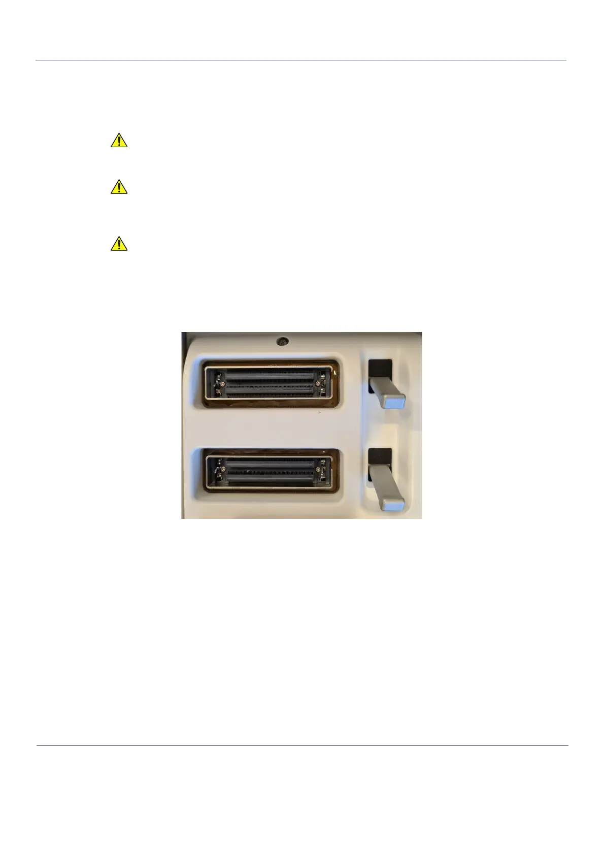
There are 2 probe connectors on the rear side of the system. Each connector is comprised of a probe-
socket and a locking latch.
Before connecting the probe:
a.) Do a visual check of the probe pins and system sockets.
b.) Remove any dust or foam rests from the probe pins.
c.) Verify the probe and the probe cable for any visual damage.
Do not allow the probe head to hang freely. Excessive impact
to the probe will result in irreparable damage.
To prevent probe connector pins damage, or PCB board
damage, do not use excessive force when connecting the
probes.
Keep the probe cables away from the wheels.
Do not bend the probe cables.
Do not cross cables between probes.

 Loading...


