EasyManuals Logo

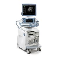
GE Voluson E8 Service Manual

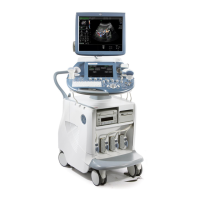
GE Voluson E8
432 pages
To Next Page IconTo Next Page
To Previous Page IconTo Previous Page
Page #210 background imageLoading...
Page #210 background image
GE HEALTHCARERAFT VOLUSON E8 / VOLUSON E6
D
IRECTION KTD102576, REVISION 7 DRAFT (AUGUST 23, 2012) SERVICE MANUAL
5-26 Section 5-3 - FrontEnd Processor
5-3-1 RTF- Probe Connector Board (cont’d)
Figure 5-7 Voluson E6: RTF + Beamformer (RTM)
RST Transmitter Subboard
RSR Receiver Subboard
+
RST Transmitter Subboard
RSR Receiver Subboard
+
RTF Probe Controlboard
Power
MOT - signals
CTRL - signals
Tx/Rx
Power
MOT - signals
CTRL - signals
Tx/Rx
Power
MOT - signals
CTRL - signals
Tx/Rx
256 Tx/Rx Channels (Rx Channels multiplexed)
SIN-COS, Mot-Strobes
CTRL-signals
PowerSupply
RTK Motherboard
EBF_D (18)
Probe 3 Probe 1Probe 2
RTM Beamformer Motherboard
RSW CW-Doppler Board
Rx /Tx
CW Probe
CH 129
CH 1
CH 1
CH 128
CH 256
CH 256
Voluson E6 - BT09
8 x RSR-Boards (16 channels) = 128 channels
16 x RST-Boards (16 channels) = 256 channels
32 Tx/Rx
Channels
CH 98 ... CH 128
1 channel
Voluson E6 - BT09
Voluson E6 - BT10
Voluson E6 - BT10
8 x RSR-Boards (16 channels) = 128 channels
12 x RST-Boards (16 channels) = 192 channels

Table of Contents

Other manuals for GE Voluson E8

Questions and Answers:

Question and Answer IconNeed help?

Do you have a question about the GE Voluson E8 and is the answer not in the manual?

GE Voluson E8 Specifications

General IconGeneral
TypeUltrasound System
3D/4D ImagingYes
ConnectivityDICOM, USB, Ethernet
Power Requirements100-240 V AC, 50/60 Hz
ApplicationsObstetrics, Gynecology, Cardiology
Doppler ModesColor Doppler, Power Doppler, Pulsed Wave Doppler
Transducer Ports4 active transducer ports
Image StorageInternal hard drive, USB storage
Transducer TypesLinear, Endocavitary
PortabilityCart-based system
Display19-inch high-resolution LCD monitor

Related product manuals