ThissectioncontainsalistoftheTechnicalSpecificationsforthe600Controller.
5 • TECHNICAL SPECIFICATIONS
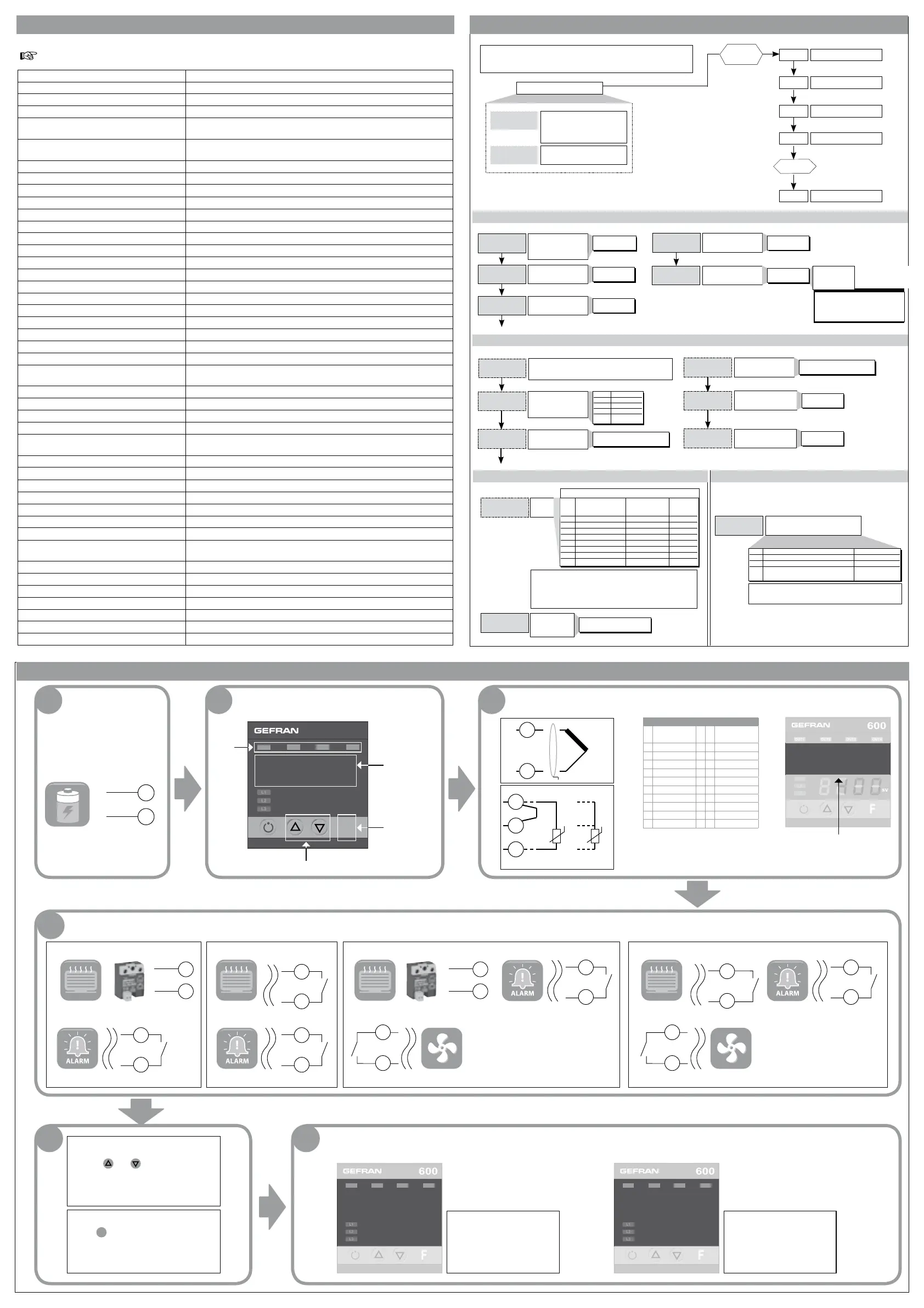
7• QUICK START GUIDE
6 • “EASY” PROGRAMMING and CONFIGURATION
al.1
P.V. / S.V.
P.V./S.V.
Processvariable(PVdisplay)
WorkSetpoint(SVdisplay)or
controloutputvaluewithcontroller
inmanual
Alarmpoint1(scalepoints)
LEVEL 1 MENU
• CFG
• InP
h.pb
h.it
h.dt
h.p.x
Xy.i
Proportionalband
forheatingor
hysteresis
inregulationON/OFF
Integraltime
forheating
Derivativetime
forheating
Maximumpowerlimit
forheating
0...999.9%
fullscale
0.00...99.99
min
0.00...99.99
min
0.0...100.0%
Alarm1hysteresis
±999
scalepoints
typ.
Probetype,signal,enablecustomlinearization,andmain
inputscale(See type table, page 6)
dp.s
lo.s
Decimalpointposition
formaininputscale
Minimumlimitofmain
inputscale
Maximumlimitofmain
inputscale
dP_S Format
0 xxxx
1 xxx.x
2 xx.xx
3 x.xxx
min...maxinputrange
selectedintyP
min...maxinputrange
selectedintyP
xi.s
xi.l
lo.l
Lowerlimitforlocal
setpointandabsolute
alarms
Lo.S...Hi.S
Upperlimitforlocal
setpointandabsolute
alarms
Lo.S...Hi.S
Alarm
type1
AL.x.t Direct(highlimit) Absolute Normale
Inverse(lowlimit) orrelative Symmetrical
toactivesetpoint (window)
0 direct absolute normal
1 inverse absolute normal
2 direct relative normal
3 inverse relative normal
4 direct absolute symmetrical
5 inverse absolute symmetrical
6 direct relative symmetrical
7 inverse relative symmetrical
AL.1.t, AL.2.t, AL.3.t
a1.t
(t.2
Cycletimefor
Out2
(HeatorCool)
1...200sec.
Pro
Protectioncode
Prot Display Modification
0 SP,alarms SP,alarms
1 SP,alarms SP
2 SP
+4 todisableInP,Out
+8 todisableCFG
+128enablesfullconfiguration
THEEASYCONFIGURATIONISSUITABLEFORVERSIONS
WITHTWOOUTPUTS(OUT1,OUT2).TOACCESSTHEOTHER
PARAMETERS,ADD128TOTHEProVALUE.
+8todisableatpower-onuntilfirstalarm
+16toenablealarmmemory
+32Hysbecomesdelaytimewhenalarmtrips(0...999sec.)
(excludingsymmetricalabsolute)
+64Hysbecomesdelaytimewhenalarmtrips(0...999min.)
(excludingsymmetricalabsolute)
InP
Out
PAS=99
Pro
Inputsettings
Outputsettings
PAS
Custommenu
Password
Protectioncode
CFG
S4Jumper
(CPU)
ON
0...999sec.
If+32inA1.t
0...999min.
If+64inA1.t
Withthetimescales
0-999sec/0-999minthedecimal
pointhasnomeaning
(fordP.Sdifferentfrom0”)
• Out
• Prot
1 2 3
FIRST STEPS DESCRIPTION 1.INPUT CONNECTION
·Openthepackage
·Powerupthedeviceaccording
tothe“Supply”informationon
thelabel.
Output
states
Changeparametervalue
Scanmenu/
parameters
Sbr- Err
forsensornot
connectedor
inshort
~
600
ouT1
ouT2 ouT3
PV
SV
ouT4
F
8888
8888
400
TC
+
-
2
1
Pt100
3
1
2
Pt1003
wires
PTC/NTC/
Pt1002wires
T
T
Ifthecorrectvalueoftheinput
(forexample,temperature)
isnotdisplayed,checkthe
connections.
PV
Input programming
-
tyP parameter
-On
Inpmenu
Input sensor
Sensor
type
Sensor
type
0 TCJ°C 30 PT100°C
1 TCJ°F 31 PT100°F
2 TCK°C 32 JPT100°C
3 TCK°F 33 JPT100°F
4 TCR°C 34 PTC°C
5 TCR°F 35 PTC°F
6 TCS°C 36 NTC°C
7 TCS°F 37 NTC°F
8 TCT°C 44 4...20mA
9 TCT°F 46 0...10V
23
~
24
Electrical
energy
CONNECTING OUTPUTS ACCORDING TO ORDER CODE
4
600-R-D-X-X-X
19
-
+
20
19
-
+
20
21
22
19
20
Alarm
21
22
Alarm
21
22
Alarm
21
22
600-R-R-X-X-X
Alarm
600-R-D-R-X-X 600-R-R-R-X-X
19
20
HeatingHeatingHeatingHeating
Solidstate
powerunit
Solidstate
powerunit
5 6
1.CHECKING OUTPUT OPERATION
H: LEDOUT2ON
AL1:LEDOUT1 OFF
C: LEDOUT3OFF
H: LEDOUT2 OFF
AL1: LEDOUT1 ON
C: LEDOUT3 ON
PROGRAMMING SP
Usethe and buttonstosetthe
controlreferencevalue(SV)onthemain
page.(seepoint2DESCRIPTION)
PROGRAMMING AL1
Press
F
onceonthemainpage:you
willseeAL.1,whichletsyouchangethe
referencevalueofAlarm1.
ouT1
ouT2 ouT3
PV
SV
ouT4
ouT1
ouT2 ouT3
PV
SV
ouT4
35 15
25 25
SetSP=AL1= PV+10,
wait20seconds,andcheckthe
stateoftheLEDs.
SetSP=AL1= PV-10,
wait20seconds,andcheckthe
stateoftheLEDs.
Cooling
5
6
ToenabletheCoolingoutputit
isnecessarytosetthefollowing
parameters
[tr= 8 (krd menu)
rl.3 =1 (0vt menu)
Cooling
5
6
ToenabletheCoolingoutputit
isnecessarytosetthefollowing
parameters
[tr= 8 (krd menu)
rl.3 =1 (0vt menu)
Display 2x4digits,green,height10and7mm
Keys 4mechanicalkeys(Man/Auto,INC,DEC,F)
Accuracy 0.2%f.s.±1at25°Croomtemperature
Thermaldrift 0.005%f.s./°C
Maininput(configurabledigitalfilter)
TC,RTD,PTC,NTC60mV,1VRi≥1MW;5V,10VRi≥10KW;20mARi=50W
Samplingtime120msec.
TypeTC(Thermocouples)(ITS90) J,K,R,S,T(IEC584-1,CEIEN60584-1,60584-2)
acustomlinearizationcanbeinserted
Coldjunctionerror 0.1°/°C
RTDType(temperatureresistance)(ITS90) Pt100(DIN43760),JPT100
Max.lineresistanceforRTD
20W
PTCType/NTCType
990W,25°C/1KW,25°C
Safety detectionofshortcircuitoropeningofprobes,LBAalarm,HBalarm
°C/°Fselection configurablefromfaceplate
Linearscaleranges -1999...9999,withconfigurabledecimalpointposition
Controls Pid,Autotune,on-off
pb-dt-it 0.0...999.9%-0.00...99.99min-0.00...99.99min
Action heat/cool
Controloutputs on/off,continuous
Max.powerlimitheat/cool 0.0...100.0%
Cycletime 0...200sec
Mainoutputtype relay,logic,continuous(0...10V/4...20mA)
Softstart 0.0...500.0min
Faultpowersetting -100.0...100.0%
Automaticblanking maintainsPVvaluedisplay,optionalexclusion
Configurablealarms upto3alarmfunctionsassignabletoanoutputandconfigurableof
type:maximum,minimum,symmetrical,absolute/relative,LBA,HB
Alarmmasking exclusionduringwarmup,memory,resetfromfaceplateand/orcontact
Typeofrelaycontact
NO(NC),5A,250V/30Vdccosj=1
Logicoutputforstaticrelays 24V±10%(10Vminat20mA)
Triacoutput 20...240Vac±10%,1Amax,inductiveandresistiveloadI
2
t=128A
Isolateddigitaloutput OpticallyisolatedMOSoutput,1500Vrms,equivalenttoanNOcontrol,max
40VAC/DCImax100mA,ResistanceONmax0.8W
Transmitterpowersupply 24Vdc,max30mAshort-circuitprotection
Analogueretransmission
10V/20mARloadmax500W12bitresolution
Digitalinputs
Ri=4,7KW(24V,5mA)orfromterminalnotsuppliedwithpower
Serialinterface(optional) RS485,isolated
Baudrate 1200,2400,4800,9600,19200
Protocol GefranCENCAL/MODBUS
Amperometricinputoption
C.T.50mAac,50/60Hz,Ri=10W
Powersupply(switchingtype) (standard)100...240Vac/dc±10%Vac50/60Hz
(optional)11...27Vac/dc±10%10VAmax
Faceplateprotection IP65
Working/Storagetemperaturerange 0...50°C/-20...70°C
Relativehumidity 20...85%Urnon-condensing
Environmentalworkingconditions forindooruse,altitudesupto2000m
Installation panel,removablefaceplate
Installationspecifications installationcategoryII,pollutionlevel2,doubleisolation
Weight 160g(completeversion)

 Loading...


