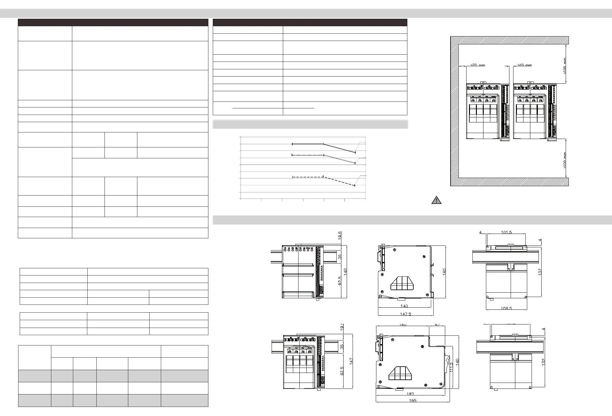
DIMENSIONS
TECHNICAL CHARACTERISTICS / GENERAL DATA FIXING / INSTALLATION
GENERAL DATA
Power supply 24Vdc ±25%, Class II, max 8VA
Fan power supply 24Vdc ±10%, 500mA @ 25Vdc
Signals Eight LEDs:
RN run state of CPU ER error signal
DI1, DI2, state of digital inputs O1...O4 state of SCR control
Protection IP20
Work/storage temperature 0…50°C (refer to dissipation curves) / -20 °C - +70 °C
Relative humidity 20…85% RH non-condensing
Ambient conditions for use indoor use, altitude up to 2000m
Installation DIN bar EN50022 or panel with screws
Installation requirements Installation category II, pollution level 2, double isolation
Max. temperature of air surrounding device 50°C Device type: “UL Open Type”
Weight Models 30KW, 60KW, 80KW
Models 30KW, 60KW with fuses
1200 g.
1600 g.
External EMC filters
The need to use a filter to obtain emissions conducted on the line during power-on of SCRs with phase angle trigger depends on
the applications.
It is important to connect the power filter as close as possible to the solid-state power unit.
We recommend a filter with the following characteristics:
Voltage Load voltage
Current Max. current on load
Rated frequency 50/60Hz
Common mode attenuation >35dB@100KHz >60dB from 150KHz to 1.5MHz
Differential mode attenuation >50dB@100KHz >60dB from 150KHz to 1.5MHz
The following are two commercial filters tested in single-phase applications:
Model Load 230V Load 400V
GFX4-IR 30KW ICAR FL140.30.00 ICAR FL140.30.00 H
GFX4-IR 60-80KW ICAR FL140.50.00 ICAR FL140.50.00 H
The CE declaration of conformity is available on request.
Model without fuse holder
Model with fuse holder
Attention: respect the minimum distances shown in figure to provide adequate
air circulation.
- Panel mounting and cut-out dimensions
- Installation
Model
EXTRARAPID FUSES
FUSES-HOLDER
ISOLATORS
Size
I²
t
Code
Format
Model
Code
Power
Dissipated @ In
Approval
Code
GFX4-IR 30 kw
16A
150 A²s
FUS-016
10x38
FWC16A10F
338470
3,5 W
PFI-10x38
337134 UR30A@690V
GFX4-IR 60 kw
30A
675 A²s
FUS-030
10x38
FR10GR69V30
338481
4,8 W
PFI-10x38
337134 UR30A@690V
GFX4-IR 80 kw
63A
3080 A²s
FUS-063
22x58
FWP63A22F
338191
11 W
PFI-22x88
337223 UR80A@600V
POWER (SOLID-STATE RELAY)
Load type AC 51 resistive or low inductance loads
AC 55b short wave infrared lamps (SWIR)
AC 56a transformers, resistive loads with high temperature coefcient
Trigger mode
PA - load control via adjustment of ring phase angle
ZC - Zero Crossing with constant cycle time (settable in range 1-200sec)
BF - Burst Firing with variable cycle time (GTT) optimized minimum.
HSC - Half Single Cycle corresponds to Burst Firing that includes ON and OFF half-cycles.
Useful for reducing icker with short-wave IR loads (applied only to single-phase resistive or
3-phase 6-wire open delta loads).
Feedback mode V: Voltage feedback: proportional to RMS voltage value on load to compensate possible
variations in line voltage.
I: Current feedback: proportional to RMS current value on load to compensate variations in
line voltage and/or variations in load impedance.
W: Power feedback: proportional to real power value on load to compensate variations
in line voltage and/or variations in load impedance. You have to calibrate each time you
change feedback mode.
Max rated voltage 480Vac
Work voltage range 90…530Vac
Non-repetitive voltage 1200Vp
Rated frequency 50/60Hz auto-determination
Rated current AC51 non-
inductive or slightly inductive
loads, resistance furnaces
30KW
4x16A
60KW
4x32A (4x30)*
80KW
4x40A (4x40)*
(single channel 57A ∑I= 160A)
Nominal current AC55b
short wave infrared lamps
30KW
4x8A
60KW
4x16A
80KW
4x20A
for applications in which you can set a minimum power output limit (ex: Lo.P = 10%) by also
limiting the lamp power variation speed with gradient limit (ex: G.out = 20%, PS.TM = 20s).
Under these conditions, the nominal currents shown on the table can be raised up to the
values indicated for AC51 type loads.
Rated current AC56A load tran-
sfomar permitted trigger modes:
ZC, BF with DT (Delay Triggering),
PA with sofstart
30KW
4x12A
60KW
4x25A
80KW
4x32A
Non-repetitive overcurrent
(t=20msec)
400A 600A 1150A
I
2
t for melting (t=1…10msec)
645A
2
s 1010A
2
s 6600A
2
s
Critical Dv/dt with output
deactivated
10,000V/ms High static dv/dt
Rated isolation voltage 4000V
* UL Certification
Current [A]
Ambient temperature [°C]
DERATING
45
40
35
30
25
20
15
10
5
0
0 10 20 30 40 50 60
GFX4-IR-80
GFX4-IR-60
GFX4-IR-30
DERATING CURVES

 Loading...


