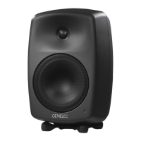
Genelec 8040-450B and 8050-450B
Genelec Flush Mount Kits are designed for
mounting Genelec 8040A or 8050A active
monitors into a wall structure. They may not
be used for any other purpose.
Preparing the installation
The wall must be prepared so that the flush
mount box can be firmly attached to the load
bearing structure. The illustrations in this
manual show the box being attached to two
horizontal 2x4” beams. The box has no pre-
arranged attachment points, so it can also be
attached by its sides or back wall.
Refer to the dimensions of the box shown
in Figures 3 and 4 overleaf when preparing
the installation. Pay attention to the following
1. In order to attach the frame correctly, the
front of the box must be flush with the final
wall surface (See Figure 1 overleaf).
2. Check that the acoustic axis alignment
of the loudspeaker is correct (it points to the
center of the listening area). The height of
the axis from the lower edge of the cutout is
shown overleaf in Figures 3 and 4. The hori-
zontal location of the axis is at the centerline
3. Ensure that the mains and signal cables
are not pinched and that there is sufficient
slack for attaching them to the loudspeaker
before the loudspeaker is placed into the
4. The cutout in the wall should not be
any bigger than what is needed to fit the
1. Drill holes in the areas of the box where
it can be attached to the support structure
and attach the box to it with screws. Figure 1
overleaf shows the box being attached to two
2. Attach the L-shaped subframe to the
loudspeaker with two M6x20 screws on the
back and an M10x20 screw at the bottom.
3. Connect the mains and signal cables to
4. Push the loudspeaker and subframe into
the box so that the studs on the subframe are
inserted into the holes on the back wall of the
5. Secure the subframe to the box with two
M6x25 (8040A) or M6x30 (8050A) screws
provided (see Figure 2 overleaf).
6. Attach the frame to the box by aligning
the guide pins to their holes and pushing the
frame in. The installation is now complete.
The frame has openings covered with felt
and is designed to leave a gap above the
loudspeaker top when installed correctly.
These are essential for the functioning of the
loudspeaker’s reflex port and amplifier cool-
ing. They must never be covered in a way
that would restrict airflow. No paint or other
treatment that may alter the characteristics
of the felt may be applied to it.