Pg 1 of 12
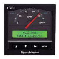
‡ SIGNET 5500 Flow Monitor
CAUTION!
Never connect 115 VAC or 230 VAC to rear
power terminals. High voltage AC will damage
instrument and void warranty.
CAUTION!
• Remove power to unit before wiring input and output
connections.
• Follow instructions carefully to avoid personal injury.
-
+
12-24 V
10 W
-
+
12 - 24 VDC
OR
12 - 24 VAC
5500
Terminals
External power
supply
‡ SIGNET 5500 Flow Monitor
ENGLISH
Technical Notes:
• To reduce the possibility of noise interference, isolate AC power lines from signal lines.
• Maximum 4-20 mA loop impedance (sec. 6) is affected by the supply voltage.
1. Power Connections
2. Compatible Sensor Wiring
Red
Black
Shld.
2000
2507
2536
2540
2550
Vortex*
Red
Black
Shld.
515
525
2517
+
GF
+
SIGNET Sensors:
Open Collector
Sensor
Std. Sensor
Freq. IN
Sen. Pwr.
Freq. IN
Iso. Gnd
5500
Terminals
= Double Insulated
= DC or AC power
Contents
1. Power Connections
2. Compatible Sensor Wiring
3. Sensor Pulse Output Connections
4. Auxiliary Pulse Output Connections
5. Totalizer Reset Connections
6. 4 - 20 mA Current Output Connections
7. Relay Connections
H (6/01) English
3-5500.090-1
8. Output Functions
9. Menu Functions
10. Parts and Accessories
11. Specifications
12. Quick Reference Menu Parameters
13. Troubleshooting
14. Maintenance
Total
reset
AUX
output
PLS
output
1
2
Gnd
+
+
-
+
Gnd
Freq. IN
Sen. Pwr.
Freq. IN
Iso. Gnd
Std. Sensor
Patent No. D376,328
Flow
Open Collector
Sensor
12-24 V
10 W
LISTED
77CJ
U
L
1 2 3 4 5 6
1 2 3 4
1
2
1 2
Total
reset
AUX
output
PLS
output
1
2
Gnd
+
+
-
+
Gnd
Freq. IN
Sen. Pwr.
Freq. IN
Iso. Gnd
Std. Sensor
Patent No. D376,328
Flow
Open Collector
Sensor
12-24 V
10 W
LISTED
77CJ
U
L
1 2 3 4 5 6
1 2 3 4
1 2
1.
2.
3.
Remove terminal blocks for easy wiring