- 22 -
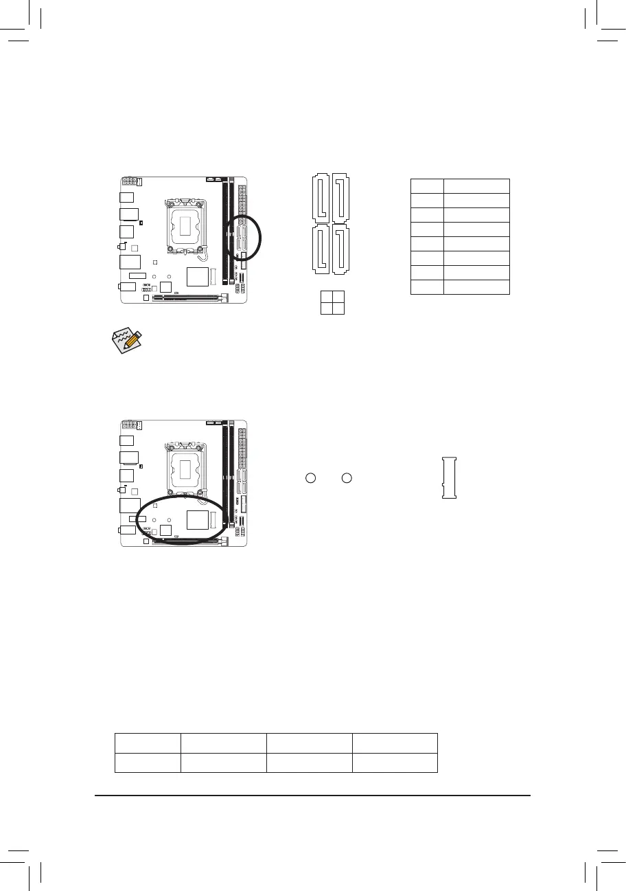
9) M2A_CPU (M.2 Socket 3 Connector)
The M.2 connector on the motherboard supports only M.2 PCIe SSDs.
Follow the steps below to correctly install an M.2 SSD in the M.2 connector.
Step 1:
Use a screwdriver to loosen the screw that secures the top heatsink to the M.2 connector and remove the
heatsink. Then remove the M.2 heatsink.
Step 2:
Locate the proper mounting hole based on the length of your M.2 SSD drive. If needed, move the standoff
to the desired mounting hole. Insert the M.2 SSD into the M.2 connector at an angle.
Step 3:
Press the M.2 SSD down and then use the included screw to secure it in the connector. Remove the
protective lm from the bottom of the M.2 heatsink and insert it back into the M.2 connector. Then screw
the top heatsink back on.
* Types of M.2 SSDs supported by the M.2 connector:
M.2 PCIe x4 SSD M.2 PCIe x2 SSD M.2 SATA SSD
M2A_CPU
a a
r
F_USB30
F_U
B_
F_ F_
_
B
BS_
B
SB_
B
_S
S_
_
B
_U
_
B
S
123
123
123
123
1
1
1
1
BSS
S
_S
SSU
1 2 3
S3
BSSS
U
__ 3
F_USB3F
S _
S _
S _
SF
B_
B_
F
_0
S
S
_0F
_F
_
_
__B
U
S _S
_
SF_
B
USB0_B
B_
B_
F_USB3
F_USB303
_
_3U
S_
_S
SS_F
_
_
80 60 42
M2A_CPU
8) SATA3 4/5/6/7 (SATA 6Gb/s Connectors)
The SATA connectors conform to SATA 6Gb/s standard and are compatible with SATA 3Gb/s and SATA 1.5Gb/s
standard. Each SATA connector supports a single SATA device. The Intel
®
Chipset supports RAID 0, RAID 1,
RAID 5, and RAID 10. Please navigate to the "Conguring a RAID Set" page of GIGABYTE's website for
instructions on conguring a RAID array.
Pin No. Denition
1 GND
2 TXP
3 TXN
4 GND
5 RXN
6 RXP
7 GND
SATA3
7 5
6 4
To enable hot-plugging for the SATA ports, please navigate to the "BIOS Setup" page of GIGABYTE's
website and search for "SATA Conguration" for more information.
1 7
7 1
 Loading...