1
2
3 4
5
6
7
8
9
10
11
12
13
14
1516171819202122
23
24
25
26
27
28
29
35
30 31 33
32
34
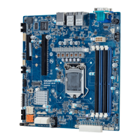
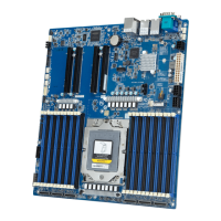
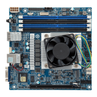
No. Code Descripon
1 MLAN Server managemnt LAN port
2 USB2_LAN1 LAN port #1 (top) / USB 3.0 ports (boom)
3 USB2_LAN2 LAN port #2 (top) / USB 3.0 ports (boom)
4 COM1_VGA Serial port (top) / VGA port (boom)
5 PMBUS PMBus connector
6 SYS_FAN1 System fan connector#1
7 P12V_AUX 8 pin power connector (for CPU)
8 CPU0 Intel LGA1151 Socket H4
9 CPU_FAN CPU fan connector
10 DIMM_P0_A0 Channel 1 slot 0
11 DIMM_P0_A1 Channel 1 slot 1
12 DIMM_P0_B0 Channel 2 slot 0
13 DIMM_P0_B1 Channel 2 slot 1
14 SYS_FAN2 System fan connector#2
15 ATX1 24 pin main power connector
16 SD_CN SD card connector
17 SATA_4 SATA 3 6Gb/s connector
18 SATA_5 SATA 3 6Gb/s connector
19 SATA_2 SATA 3 6Gb/s connector
20 SATA_3 SATA 3 6Gb/s connector
21 SATA_1 SATA 3 6Gb/s connector
22 SATA_0 SATA 3 6Gb/s connector
23 FP_2 Secondary front panel header
24 FP_1 Front panel header
25 F_USB2 USB 2.0 header
26 IPMB IPMB connector
27 TPM TPM connector
28 BP_1 HDD back plane board header
29 COM2 Serial port cable connector
30 PCIE_1 PCI Express x8 slot (running at x4)
31 PCIE_2 PCI Express x16 slot (running at x8)
No. Code Descripon
32 BAT Baery socket
33 PCIE_3 PCI Express x1 slot
34 PCIE_4 PCI Express x16 slot (running at x8)
35 LED_BMC1 BMC firmware readiness LED
HDD Back Plane Board Header/ 硬盤背板排針
1 2
25 26
No. Pin Define
1 BP_SGP_CLK
3 BP_SGP_LOAD
5 BP_SGP_DOUT
7 Key Pin
9 GND
11 BP_LED_G_N
13 BP_SGP_DIN
15 GND
17 GND
19 P_3V3_AUX
21 P_3V3_AUX
23 GND
25 BP_PRESENSE
No. Pin Define
2 No Connect
4 No Connect
6 GND
8 Reset
10 BP_LED_A_N
12 GND
14 No Connect
16 SMB_BP_DATA
18 SMB_BP_CLK
20 BMC_ACK
22 BMC_REQ
24 Key Pin
26 GND
Front Panel Header #1/ 前面板 (Server)
1
2423
2
No. Pin Define
1 Power LED+
3 No Pin
5 Power LED-
7 HDD LED+
9 HDD LED-
11 Power Buon
13 GND
15 Reset Buon
17 GND
19 ID Buon
21 GND
23 NMI Switch
No. Pin Define
2 5V Standby
4 ID LED+
6 ID LED-
8 System Status LED+
10 System Status LED-
12 LAN1 Ac ve LED+
14 LAN1 Link LED-
16 SMBus Data
18 SMBus Clock
20 Case Open
22 LAN2 Acve LED+
24 LAN2 Link LED-
Front Panel Header #2/ 前面板 (PC)
No. Pin Define
1 HDD LED+
2 Power LED+
3 HDD LED-
4 Power LED-
5 GND
1
109
2
6 Power Buon+
7 Reset Buon
8 Power Buon-
9 No Connect
10 No Pin
ATX Power/ 电源
8 4
5 1
No. Pin Define
1 GND
2 GND
3 GND
4 GND
5 +12V
6 +12V
7 +12V
8 +12V
1 12
24
13
PMBUS
1
5
No. Pin Define
1 PMBus Clock
2 PMBus Data
3 PMBus Alert
4 GND
5 3.3V Sense
Installing CPU/ 安装 CPU
Memory Populaon Configuraon/ 安装内存
All channels in system run at the fastest common frequency.
Mixing ECC and non-ECC UDIMMs anywhere on the plaorm is not supported.
1 and 2 DPC is supported at 2133MHz.
所有通道模式以最快的频率速度运行。
此主板不支持ECC与非ECC内存模组混合使用。
1 与 2 DPC 均支持2133MHz速度。
Type
Ranks Per
DIMM and
Data Width
Speed (MT/s);
Slot Per Channel (SPC) and
DIMM Per Channel (DPC)
Supported
Voltage
2 Slot Per Channel
1DPC 2DPC
UDIMM
Unbuffered
DDR4 ECC
UDIMM
Unbuffered
DDR4 non-ECC
SR 1.2V
1.2V
2133 2133
DR
2133 2133
Rear I/O Connector/ 后面板接口
No. Desripon
1 Serial port
2 VGA port
3 GbE Eternet LAN port
Off
State Description
Yellow On 1Gbps data rate
Green On 100Mbps data rate
10Mbps data rate
10/100/1000 LAN LED:
Speed LED Link/Acvity
LED
No. Desripon
4 GbE Eternet LAN port (Shared LAN port)
5 KVM Server Management 10/100/1000 LAN port
6 USB 3.0 ports
2
4
5
66
31
SATA Connector/SATA 接口
7
1
No. Pin Define
1 GND
2 TXP
3 TXN
4 GND
5 RXN
6 RXP
7 GND
IPMB
1
3
No. Pin Define
1 Clock
2 GND
3 Data
TPM Connector/ 可信平台模块
1 2
13 14
No. Pin Define
1 Clock
2 P_3V3_AUX
3 LPC_RST
4 P3V3
5 LPC_LAD0
6 IRQ_SERIAL
7 LPC_LAD1
No. Pin Define
8 No Connect
9 LPC_LAD2
10 No Pin
11 LPC_LAD3
12 GND
13 LPC_FRAME_N
14 GND
COM2 Connector
21
109
No. Pin Define
1 NDCD-
2 NSIN
3 NSOUT
4 NDTR-
5 GND
No. Pin Define
6 NDSR-
7 NRTS-
8 NCTS-
9 NRI-
10 No Pin
CPU/System FAN/ 风扇
4
1
No. Pin Define
1 GND
2 +12V
3 Sense
4 Speed Control
USB 2.0 Header
No. Pin Define
1 Power (5V)
2 Power (5V)
3 USB DX-
4 USB DY-
5 USB DX+
109
21
No. Pin Define
6 USB DY+
7 GND
8 GND
9 No Pin
10 No Connect
Jumper Sengs/ 跳线设置
No. Desripon
1 ME Update Jumper
1-2 Close: Normal operaon (Default seng)
2-3 Close: ME update mode.
2 Clear CMOS Jumper
Open: Normal operaon (Default seng)
Closed: Clear CMOS data.
3 S3 Power On Select Jumper
1-2 Close: Stop an inial power on when BMC is not ready.
2-3 Close: Keep inial power on. (Default seng)
4 Clearing Supervisor Password Jumper
1-2 Close: Normal operaon. (Default seng)
2-3 Close: Skip supervisor password.
5 ME Recovery Jumper
1-2 Close: Normal operaon. (Default seng)
2-3 Close: ME recovery mode.
6 BIOS Recovery Jumper
1-2 Close: Normal operaon. (Default seng)
2-3 Close: BIOS recovery mode.
12
3
4
5
6
MX31-CE0 Quick Reference Guide/ 快速测试参考指南
No. Pin Define
1 3.3V
2 3.3V
3 GND
4 +5V
5 GND
6 +5V
7 GND
8 Power Good
9 5VSB
10 +12V
11 +12V
12 3.3V
No. Pin Define
13 3.3V
14 -12V
15 GND
16 PS_ON
17 GND
18 GND
19 GND
20 -5V
21 +5V
22 +5V
23 +5V
24 GND
PN:12QM1-MX31B0-00R