Characteristics: Technical Data:
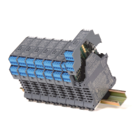
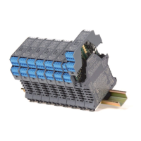
Front Panel and Features:
Ordering Information:
Model: D1033
D1033
D1033
SIL 2 Switch/Proximity Detector
Repeater Transistor Output DIN-Rail
Models D1033D, D1033Q
General Description:
The Switch/Proximity Detector Repeater type D1033 is a DIN Rail unit with two or four
independent and isolated channels. The unit can be configured for contact or proximity
detector, NO or NC and for NC or NO optocoupled open collector transistor output.
Each channel enables a Safe Area load to be controlled by a switch, or a proximity
detector, located in Hazardous Area.
D1033Q quad channel type has four independent input channels and actuates the
corresponding output transistor. Two actuation modes can be independently DIP switch
configured on each input channel: NO input/NC transistor or NO input/NO transistor.
Contact or proximity sensor and its connection line short or open circuit fault detection is
also DIP switch configurable: fault detection can be enabled (in case of fault it
de-energizes the corresponding output transistor and turns the fault LED on) or disabled
(in case of fault the corresponding output transistor repeats the input line open or closed
status as configured).
D1033D dual channel type has two input channels and four output transistors;
the unit has two DIP switch configurable operating modes:
Mode A) input channel actuates in parallel the two output transistors.
Transistor actuation mode can be independently configured for each output in two
modes: NO input/NC transistor or NO input/NO transistor.
Mode B) input channel actuates output transistor A configurable in two modes as in
mode A above. Output transistor B operates as a fault output (in case of input fault,
transistor B actuates and the fault LED turns on while transistor A repeats the input line
as configured). Actuation can be DIP switch configured in two modes:
No input fault/energized transistor (it de-energizes in case of fault) or
No input fault/de-energized transistor (it energizes in case of fault).
Function:2 or 4 channels I.S. switch repeater for contact or EN60947-5-6 proximity.
Provides 3 port isolation (input/output/supply). Line-fault detection, common to all
input signals, available when using Power Bus enclosure.
Signalling LEDs: Power supply indication (green), output status (yellow), line fault (red).
Field Configurability: NO/NC input for contact/proximitor, NC/NO transistor operation
and fault detection enable/disable.
EMC: Fully compliant with CE marking applicable requirements.
Functional Safety Management Certification:
G.M. International is certified by TUV to conform to IEC61508:2010
part 1 clauses 5-6 for safety related systems up to and included SIL3.
• SIL 2 according to IEC 61508:2010 Ed.2
for Tproof = 6 / 10 years (≤10% / >10 % of total SIF).
• PFDavg (1 year) 1.54 E-04, SFF 75.41 %.
• SIL 3 Systematic capability
• Input from Zone 0 (Zone 20), Division 1,
installation in Zone 2, Division 2.
• NO/NC contact/proximity Detector Input.
• Four opto isolated voltage free transistor
Output Signals.
• Common negative or positive output both
accepted in standard version D1033.
• Transistor Output for fault detection on
dual channel version.
• Line fault detection with common signalling
available when using Power Bus enclosure.
• Three port isolation, Input/Output/Supply.
•
EMC Compatibility to EN61000-6-2, EN61000-6-4,
EN61326-1.
• In-field programmability by DIP Switch.
• ATEX, IECEx, UL & C-UL, FM & FM-C, INMETRO,
EAC-EX, UKR TR n. 898, TÜV Certifications.
• TÜV Functional Safety Certification.
• Type Approval Certificate DNV and KR for
maritime applications.
• High Reliability, SMD components.
• High Density, four channels per unit.
• Simplified installation using standard
DIN Rail and plug-in terminal blocks.
• 250 Vrms (Um) max. voltage allowed to the
instruments associated with the barrier.
Supply:
24 Vdc nom (20 to 30 Vdc) reverse polarity protected,
ripple within voltage limits ≤ 5 Vpp.
Current consumption @ 24 V: 55 mA for 4 channels D1033Q,
35 mA for 2 channels D1033D with input closed and transistors energized.
Power dissipation: 1.3 W for 4 channels D1033Q, 0.9 W for 2 channels D1033Q
with 24 V supply voltage, input closed and transistors energized.
Max. power consumption: at 30 V supply voltage, short circuit input and
transistors energized, 1.5 W for 4 channels D1033Q, 1.1 W for 2 channels D1033D.
Isolation (Test Voltage):
I.S. In/Out 1.5 KV; I.S. In/Supply 1.5 KV; I.S. In/I.S. In 500 V;
Out/Supply 500 V; Out 1-3/Out 2-4 500 V.
Input switching current levels:
ON ≥ 2.1 mA, OFF ≤ 1.2 mA, switch current ≈ 1.65 mA ± 0.2 mA hysteresis.
Fault current levels: open fault ≤ 0.2 mA, short fault ≥ 6.8 mA
(when enabled both faults de-energize channel transistor with quad channel
unit D1033Q or actuate fault transistor with dual channel unit D1033D).
Input equivalent source: 8 V 1 KΩ typical (8 V no load, 8 mA short circuit).
Output:
voltage free SPST optocoupled open-collector transistor.
Open-collector rating: 100 mA at 35 V
(≤ 2.5 V voltage drop or ≤ 1.0 V voltage drop for versions -052 and -058).
Leakage current: ≤ 50 µA at 35 V.
Response time: 500 µs.
Frequency response: 2 KHz maximum.
Compatibility:
CE mark compliant, conforms to Directive:
2014/34/EU ATEX, 2014/30/EU EMC, 2014/35/EU LVD, 2011/65/EU RoHS.
Environmental conditions:
Operating: temperature limits -20 to + 60 °C, relative humidity max 95%.
Storage: temperature limits – 45 to + 80 °C.
Safety Description:
ATEX: II (1) G [Ex ia Ga] IIC, II (1) D [Ex ia Da] IIIC,I (M1) [Ex ia Ma] I, II 3G Ex nA IIC T4 Gc
IECEx / INMETRO: [Ex ia Ga] IIC, Ex ia [Ma] I, [Ex ia Da] IIIC, Ex nA IIC T4 Gc
UL: NI / I / 2 / ABCD / T4, AIS / I, II, III / 1 / ABCDEFG, AEx nC [ia] IIC
C-UL: NI / I / 2 / ABCD / T4, AIS / I, II, III / 1 / ABCDEFG, Ex nC [ia] IIC
FM: NI / I / 2 / ABCD / T4, NI / I / 2 / IIC / T4, AIS / I, II, III / 1 / ABCDEFG, AEx [ia] IIC
FM-C: NI / I / 2 / ABCD / T4, NI / I / 2 / IIC / T4, AIS / I, II, III / 1 / ABCDEFG, Ex [ia] IIC
EAC-EX: 2Ex nA [ia Ga] IIC T4 Gc X, [Ex ia Da] IIIC X, [Ex ia Ma] I X
UKR TR n. 898: 2ExnAiaIICT4 X, ExiaI X
associated electrical apparatus.
Uo/Voc = 9.6 V, Io/Isc = 10 mA, Po/Po = 24 mW at terminals13-14, 15-16, 9-10, 11-12.
Um = 250 Vrms, -20 °C ≤ Ta ≤ 60 °C.
Approvals:
DMT 01 ATEX E 042 X conforms to EN60079-0, EN60079-11, EN60079-26.
IECEx BVS 07.0027X conforms to IEC60079-0, IEC60079-11, IEC60079-26,
IMQ 09 ATEX 013 X conforms to EN60079-0, EN60079-15,
IECEx IMQ 13.0011X conforms to IEC60079-0, IEC60079-15
INMETRO DNV 13.0108 X conforms to ABNT NBR IEC60079-0, ABNT NBR IEC60079-11,
ABNT NBR IEC60079-15, ABNT NBR IEC60079-26.
UL & C-UL E222308 conforms to UL913, UL 60079-0, UL60079-11, UL60079-15
ANSI/ISA 12.12.01 for UL and CSA-C22.2 No.157-92, CSA-E60079-0, CSA-E60079-11,
CSA-C22.2 No. 213 and CSA-E60079-15 for C-UL.
FM & FM-C No. 3024643, 3029921C, conforms to Class 3600, 3610, 3611, 3810,
ANSI/ISA 12.12.02, ANSI/ISA 60079-0, ANSI/ISA 60079-11, C22.2 No.142,
C22.2 No.157, C22.2 No.213, E60079-0, E60079-11, E60079-15,
C-IT.MH04.B.00306 conforms to GOST R IEC 60079-0,GOST R IEC 60079-11,
GOST R IEC 60079-15.
CЦ 16.0034 X conforms to ДСТУ 7113, ГОСТ 22782.5-78, ДСТУ IЕС 60079-15.
TÜV Certificate No. C-IS-236198-03, SIL 2 conforms to IEC61508:2010 Ed.2.
TÜV Certificate No. C-IS-236198-09, SIL 3 Functional Safety Certificate conforms to
IEC61508:2010 Ed.2, for Management of Functional Safety.
DNV No.A-13778 and KR No.MIL20769-EL001 Certificates for maritime applications.
Mounting:
T35 DIN Rail according to EN50022.
Weight: about 165 g D1033Q, 140 g D1033D.
Connection: by polarized plug-in disconnect screw terminal blocks to accomodate
terminations up to 2.5 mm
2
.
Location: Safe Area/Non Hazardous Locations or Zone 2, Group IIC T4,
Class I, Division 2, Groups A, B, C, D Temperature Code T4 and
Class I, Zone 2, Group IIC, IIB, IIA T4 installation.
Protection class: IP 20.
2 channels D
G.M. International DTS0151-18 Page 1/2
1 2 3 4
9 10 11 12
16 15 14 13
Common negative and positive
4 channels
Q
-052
5 6 7 8
PWR ON
1 2
STATUS/
FAULT
3 4
Common negative only
Common positive only
Power Bus enclosure
blank
-058
/B
www.gmintsrl.com
FSM
SIL 3
Power Bus and DIN-Rail accessories:
DIN rail anchor MCHP065 DIN rail stopper MOR016
Terminal block male MOR017 Terminal block female MOR022