[page 6] | gpelectric.com
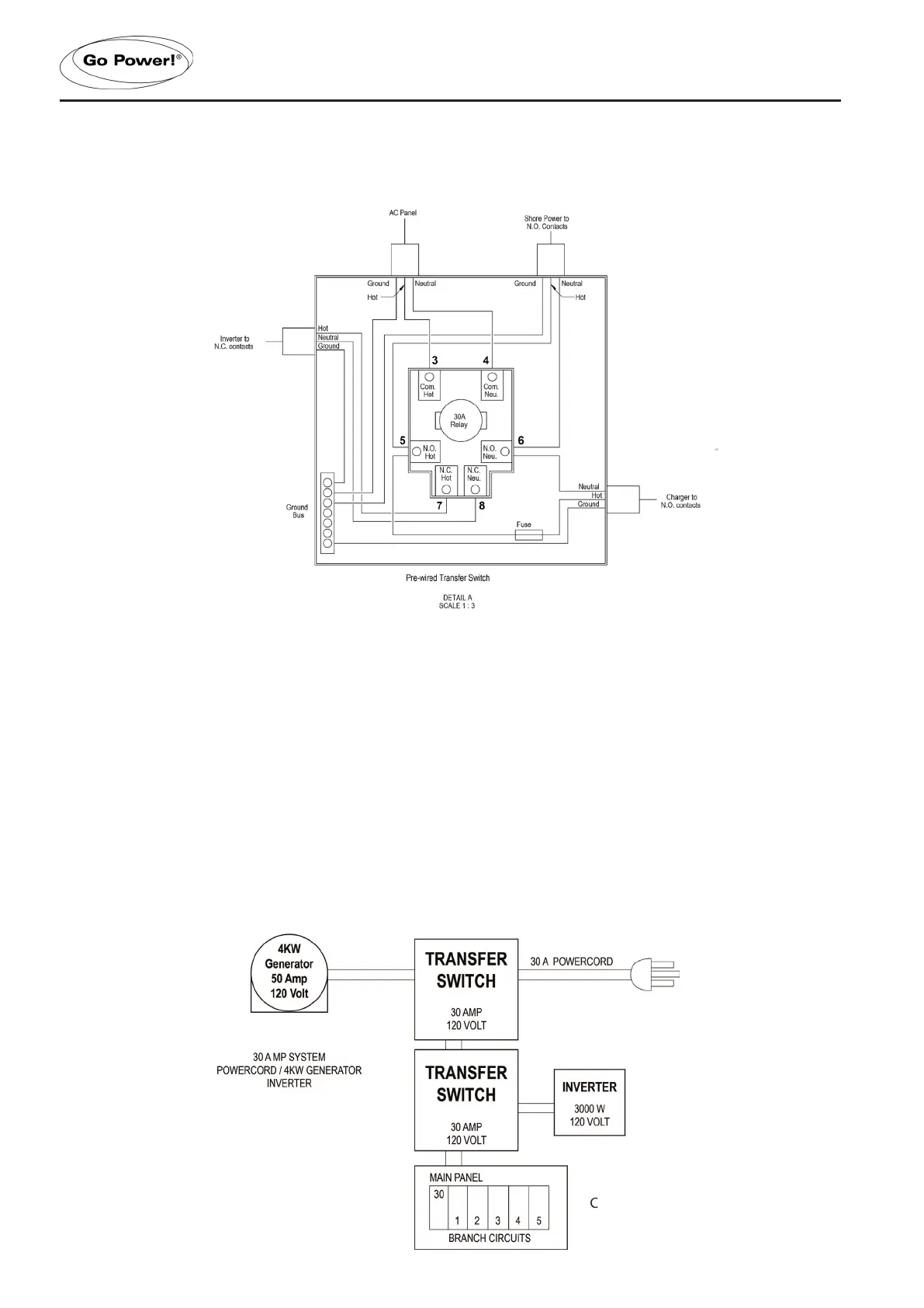
Diagram 1 – Typical Generator Power Cord Connection
2.5.2 INSTALLATION BETWEEN INVERTER AND ALTERNATING SOURCE
(CONFIGURATION C)
1. For installation between inverter (default) and another power supply (dominant), such as the output from a prior power
cord/ generator transfer switch. These connections will allow any other supply to dominate the inverter, and the inverter
output will pass through the normally closed contacts of the switch. This allows the inverter to operate only in the
absence of the other power supplies, which is ideal for inverters. Three AC sources require two transfer switches.
2. Connect the inverter to terminals 7 and 8, and connect the other power supply (output from the rst transfer switch) to 5
and 6. Output terminals always remain the same. (See Diagram 1 above for number locations)
INSTALLATION
#1
#2
 Loading...