GRAUPNER GmbH & Co. KG D-73230 KIRCHHEIM/TECK GERMANY
Modifications reserved. No liability for printing errors. 08/2011
- 4 -
This picture shows the completed aileron linkage. Please note that the servo output
arm should be at least 12 mm long, otherwise the clevis will foul the wing surface.
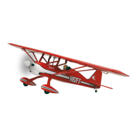
The photo shows the servo extension lead projecting out of the underside of the
wing. Note that the lead should first be run straight out of the opening in the root rib,
and then doubled-back to pass through the hole in the underside. Carefully open up
the hole in the wing using a sharp balsa knife.
The fuselage and tail
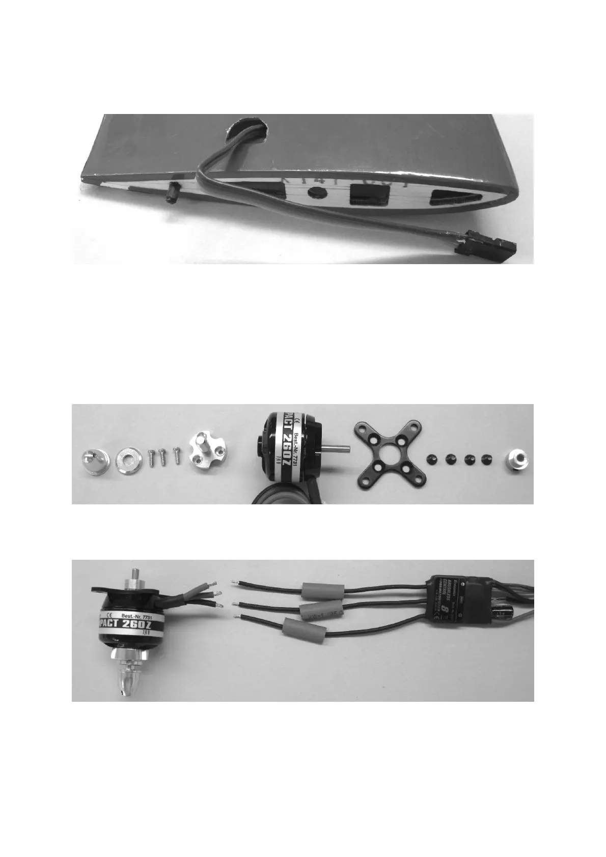
Attach the propeller driver, the cruciform mount and the retaining collet to the motor;
you will find these parts in the pack of Order No. 7731.
The picture shows the component parts of the propeller driver and motor mount; take
care to tighten all the screws fully.
This picture shows the motor with the cruciform mount and the propeller driver fitted.
Cut the motor wires to length, and strip the ends for a length of about 5 mm. Slip
separate pieces of heat-shrink sleeve (included in Order No. 7731) over the three
wires. Tin all the bare wire ends before soldering the pairs together in any order. Slip
 Loading...