GB - 11
UNPACK UNIT
Remove all packing materials and hardware
and literature packages. Discard J hook used
with strapping as it is not needed for mower
operation.
SETUP INSTRUCTIONS
Gravely mowers are shipped partially
assembled. After uncrating the power unit
and mower deck, initial setup is required.
IMPORTANT: During the unpacking of the
crate all goods should be matched against
the packing list and all shortages or damages
should be noted and reported to the carrier
immediately.
Steering Controls
1. The steering control levers may have
been loosened and moved forward for
shipping. Remove the loose 3/8-16 x
1.75" bolts from the handles and reinstall
them in the location shown. Adjust the
handles to fit your comfort area.
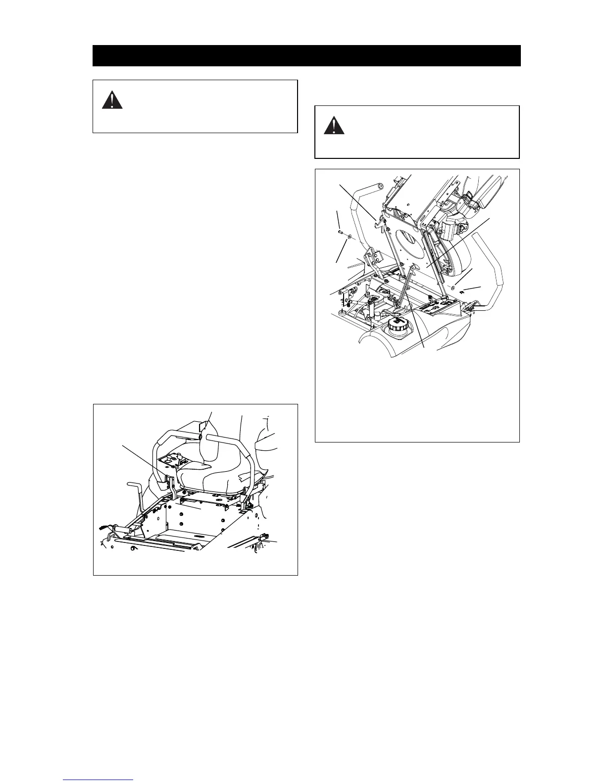
Seat Setup
1. Remove the loose 3/8" clevis pin, two
flat washers and rue ring from the
manual pack.
2. Carefully rotate the seat plate forward
far enough to install the seat support bar
in the location shown in figure 4.
3. Connect the seat suport bar to the
bottom of the seat plate using the 3/8"
clevis pin, two 3/8" flat steel washers
and the rue ring.
4. Return seat plate to operating position
and engage seat lock.
Battery
The battery supplied with the mower is
sealed, it will not be necessary to activate it.
1. Connect the red positive cable to the
positive (+) side of battery. Use 1/4 x
5/8" bolt and 1/4" locknut. Cover
terminal with rubber boot.
2. Connect the black negative cable to
Negative ( - ) side of battery. Use 1/4 x
5/8" bolt and 1/4" locknut.
If the engine does not turn over by turning the
ignition switch, it may be necessary to charge
the battery. (See Charging the Battery on
page 32.)
Deck
1. Remove knob from discharge shield.
2. Remove discharge assembly from
Transport position.
3. Install discharge assembly in Operating
position.
4. Reinstall knob in discharge assembly
and tighten.
ASSEMBLY
WARNING: AVOID INJURY!
Read and understand entire
Safety Section before
proceeding.
Figure 3
Install
Bolt
Here
CAUTION: Ensure that seat lock
is latched and fully engaged
when returning seat plate to
operating position.
Figure 4
1. Seat Support Bar
2. Seat Plate
3. Seat Lock
4. 3/8 in. Clevis Pin
5. Flat Washer
6. Rue Ring
1
3
4
5
6
5
2
 Loading...