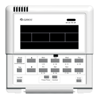
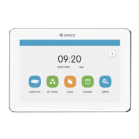
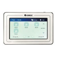
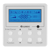
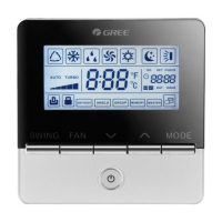
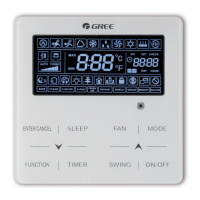
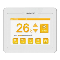
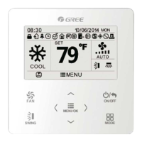
Centralized Controller
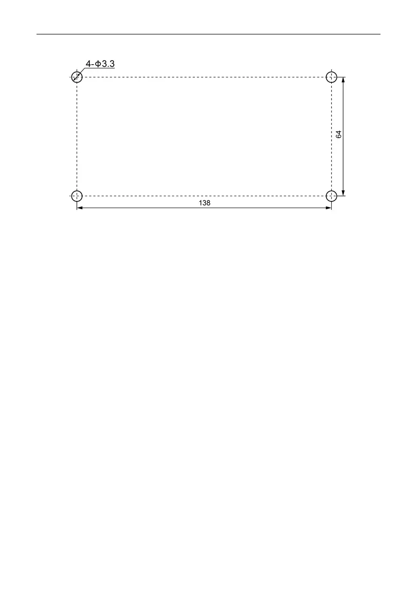
Unit:mm
Fig. 3.13 Installation Holes of the Electric Box Rear Cover
Fig.3.11 is a simple installation procedure of centralized controller. Please pay
attention to the following matters:
(1) Before installation, first cut off the power supply of indoor unit. The power must
be cut off during the whole installation process.
(2) During the installation, be careful not to damage to touch screen.
(3) Before installation, please make the following preparations:
1) In case that the centralized controller is installed on wall, dig a hole that is
the size of 180mm×107mm×62mm and peg 4 wooden or plastic plugs on
the wall according to fig.3.12.
2) In case that the centralized controller is installed inside the control cabinet,
dig 4 installation holes on the surface of the control cabinet according to
fig.3.13.
(4) In step
①
, pull out the power core and communication cord, and then lead
them separately from the wire orifice of the electric box rear cover. Never lead
the cords through a same orifice.
(5) In step
①
, pull out the power core and communication cord, and then lead
them separately from the wire orifice of the electric box rear cover. Never lead
the cords through a same orifice.
(6) In step
⑥
pull out the wire connecting the touch screen and controller’s rear
cover. Put the touch screen on a safe place.
 Loading...