-1-
-2-
-3-
WARNING !
①
All installation and commissioning shall be performed by the qualied serviceman in accordance
with instructions covered in the manual, otherwise it would cause water leakage, electric shock
or re hazard etc.
②
The unit shall be wired as per the wiring diagram, otherwise the electric motor would be burned
out.
③
The unit shall be grounded reliability to avoid hurt on the human body or damage on properly due
to poor insulation.
④
Before obtaining access to terminals, all supply circuits must be disconnected.
User Notice
This appliance is intended to be used by expert or trained users in shops, in light industry and on
farms, or for commercial use by lay persons.
DISPOSAL: Do not dispose this product as unsorted municipal waste. Collection of
such waste separately for special treatment is necessary.
This appliance can be used by children aged from 8 years and
above and persons with reduced physical, sensory or mental
capabilities or lack of experience and knowledge if they have been
given supervision or instruction concerning use of the appliance
in a safe way and understand the hazards involved.Children shall
not play with the appliance. Cleaning and user maintenance shall
not be made by children without supervision.
1 APPLICATION SCOPE
(1) The entering water temperature for cooling shall not be lower than 5°C, otherwise it would
cause sweating on the surface of the unit. The entering water temperature for heating shall not
be higher than 80°C(60°C), otherwise it would corrode the copper tube .
(2) The range of the ambient temperature for cooling shall be 16-40°C and be 10-35°C for heating.
The relative humidity shall be or less than 95%.
(3) The unit is categorized into the comfort air conditioning unit and shall not be installed where
there is corrosive, inammable gas or smog (like, kitchen) and wet (like, laundry), otherwise
the unit would fail to operate properly and the service life would be shortened.
(4) The A-weighted sound pressure level is below 70dB.
2 INSTALLATION INSTRUCTIONS
(1) The unit shall be installed by the skilled servicemen who have well knowledge of this product
and also the local laws and regulations.
(2) See the gures below for installation dimensions. (Unit: mm)
Slotted Hole
L
L+36
a
b
4-10×20
302
88
30
163.6
191
235
227
WA-K Series L a b WA-K Series L a b
FP-34WA(H)-K 490 45 310 FP-102WA(H)-K 820 45 310
FP-51WA(H)-K 620 45 310 FP-136WA(H)-K 1400 75 250
FP-68WA(H)-K 740 45 310 FP-170WA(H)-K 1400 75 250
FP-85WA(H)-K 820 45 310 FP-204WA(H)-K 1400 75 250
WAS Series L a b WAS Series L a b
FP-34WAS-R 490 45 310 FP-102WAS-R 980 45 310
FP-51WAS-R 620 45 310
FP-136WAS-R 1400 75 250
FP-68WAS-R 740 45 310
FP-170WAS-R 1500 75 310
FP-85WAS-R 820 45 310 FP-204WAS-R 1500 75 310
F-T Series L a b F-T Series L a b
FP-34WAF(T)-R 490 45 310 FP-102WAF(T)-R 980 45 310
FP-51WAF(T)-R 620 45 310 FP-136WAF(T)-R
1400 75 250
FP-68WAF(T)-R 740 45 310 FP-170WAF(T)-R
1500 75 310
FP-85WAF(T)-R 820 45 310 FP-204WAF(T)-R 1500 75 310
ab
Slotted Hole
4-10×20
220
L+36
L
115
350
340
287.5
230
325
588
WAS Series L a b F-T Series L a b
FP-238WAS-R 1250 68 284 FP-238WAF(T)-R 1250 68 284
FP-272WAS-R 1250 68 284 FP-272WAF(T)-R 1250 68 284
FP-306WAS-R 1500 68 284 FP-306WAF(T)-R 1500 68 284
FP-340WAS-R 1500 68 284 FP-340WAF(T)-R 1500 68 284
245
191
235
225
130
30163.6
88
310 L+36 45
L
476
302
Slotted Hole
4-10×20
WA-K Series L
FP-51WA5S-K 620
FP-68WA5S-K 740
FP-102WA5S-K 820
(3) The unit shall be installed securely. When installing hanger bolts, be sure they are capable of
withstanding 4 times the weight of the unit. If unsure, they shall be reinforced. The weight of
the unit is specied on the nameplate.
(4) Enough service space shall be left around the unit as shown in the gure below.
>0.3m
>0.25m
(5) The drain pan shall tilt toward the drain outlet with a desired downward slope. Hanger bolts are
only intended to bear the weight of the unit other than the outside force of the duct, water pipe
and others.
(6) The length of the duct shall be compatible with the rated static pressure, otherwise the unit
would fail to run properly. The inlet and outlet of the duct shall be attached with flexible
connections.
(7) Water pipes shall be cleaned up prior to installation, and the outlet shall be equipped with a
lter to prevent valves from being clogged by foreign matters.
(8) The unit shall be protected again dust during installation.
(9) A filter shall be installed at the return air inlet and be cleaned frequently to guarantee the
expected heat exchange efciency.
(10) The duct shall comply with requirements stated below.
1) The duct shall be designed and installed as per the applicable local standards.
2) The duct shall be designed so that its sectional area won’t change suddenly and the air
direction won’t change at the outlet.
3) The duct shall be insulated reliably to prevent sweating under the cooling operation.
(11) Water pipes shall comply with requirements stated below.
(12) The drain pipe and inlet/outlet pipe shall be with the standard threaded pipe ttings. Water
pipes shall be installed as per applicable local standards. During installation, do not over-
tighten the pipe ttings to avoid any damage on the header and connections of the coil.
1) The inlet/outlet pipe shall be installed in accordance with the applicable labels and equipped
with the quakeproof flexible connections and movable joints, as well as suitable filters
to prevent the heat exchanger from scaling which then would lower the heat exchange
efciency.
2) The inlet/outlet pipe shall be equipped with valves to control and cut off the water ow. The
weight of water pipes shall not be withstood by the main unit.
3) The inlet/outlet pipe, drain pipe and valves shall be insulated to prevent sweating under the
cooling operation in summer.
4) The condensate drain pipe should be installed downward with a slope larger than 5% to
facilitate drainage.
5) Do not drag and pull water pipes forcibly and seal them with Teflon tape to avoid water
leakage.
(13) Be sure the power supply coincides with that specied on the nameplate and is cut off prior
to electric installation. Electric wiring shall be performed in accordance with the electric wiring
diagram as shown the gure below and the unit shall be grounded reliably. The appliance shall
be installed in accordance with national wiring regulations.
(14) The power cord technical data we recommended is 0.5*3(Unit:mm
2
*ROT).
(15) If the supply cord is damaged, it must be replaced by the manufacturer, its service agent or
similarly qualied persons in order to avoid a hazard.
(16) Means for disconnection must be incorporated in the xed wiring in accordance with the wiring
rules.
(17) The appliance is intended to be permanently connected to the water mains and not connected
by a hose-set.
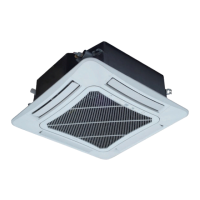
Concealed Ceiling Type Fan Coil Unit
Owner's Manual (Original Instructions)
Commercial Air Conditioners