GMV DC Inverter VRF
58
——
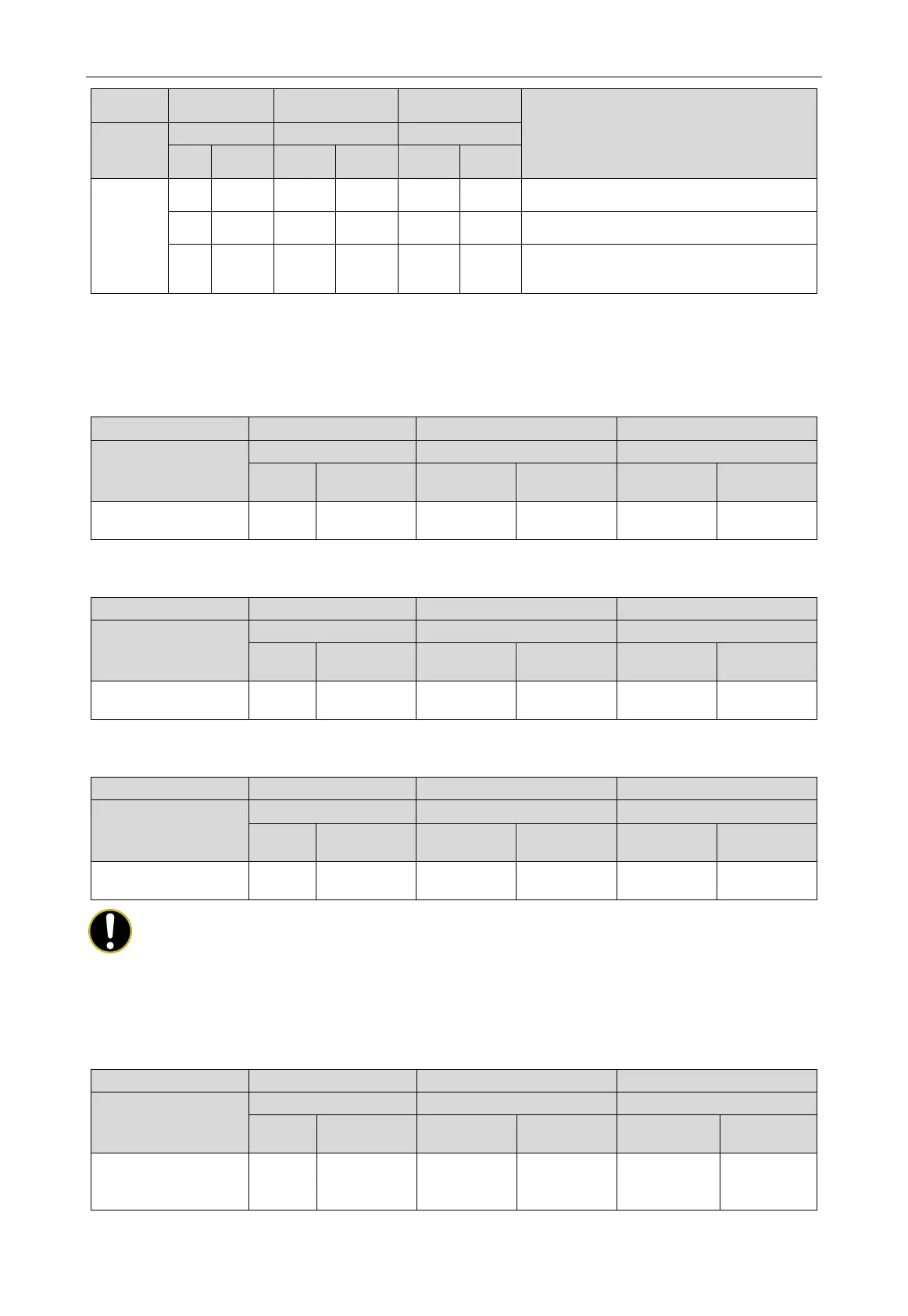
Progress code Status code
Meaning
Progress
LED1 LED2 LED3
Code
Code
Code
01_ set up
master unit
db ON 01 ON CC ON
Mater module hasn't been set in the system. It
needs to reset it.
db ON 01 ON CF ON
More than two master modules are set in the
system and it needs to reset it.
db ON 01 ON OC ON
Mater module of system has been set
successfully. Enter into the next step
According to the above fault phenomenon, reset the master module according to the setting
method of “Master Module DIP Switch Code Setting (SA8_MASTER-S)”, and re-enter into the
debugging after setting.
During the assignment process, all module digital tubes displays are as below:
Progress
LED1 LED2 LED3
Code
Display
Code
Display
Code
Display
02_ allocate
db ON 02 ON Ad Flash
Step 6: When the unit is running to step 03, it displays the number of modules connected to the
outdoor connection. At this time, the main board of each module is displayed as below:
Progress
Code
Display
Code
Display
Code
Display
03_ module quantity
db ON 03 ON
Module
Flash
After 30s of display, the automatic display is as follows; if press SW3 button within 30s, the
display is as follows. The unit automatically enters the next step of debugging:
Progress
Code
Display
Code
Display
Code
Display
03_module quantity
db ON 03 ON OC ON
NOTE!
It is important to confirm that the number of online outdoor unit modules is the same as that of
actual modules; otherwise it will need to conduct the inspection and debugging again.
Step 7: When the unit is running to step 04, the number of online connected indoor unit is
displayed. At this time, the main board of each module is displayed as below:
Progress
LED1 LED2 LED3
Code
Display
Code
Display
Code
Display
04_indoor unit
quantity confirmation
db ON 04 ON
The quantity
of online
Flash
 Loading...