146
NOTES:
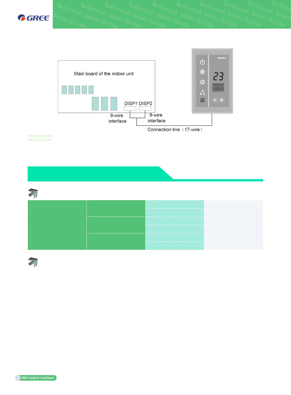
a. The wired controller and remote receiving LED panel can be used at the same time.
b. Note to select a remote controller when a remote receiving LED panel is used.
12
ELECTRICAL CONNECTION
12.1 External Connection Interfaces
External connection interfaces
Power supply
Quantity 4
Label L1 L2 L3 PE
Indoor/outdoor unit
communication
Quantity 2
Label D1 D2
Centralized control
Quantity 2
Label G1 G2
12.2 External Connection
Every unit must be configured with a circuit breaker to implement short circuit and abnormal overload
protection. Besides, the indoor unit and outdoor unit should be respectively configured with a general
circuit breaker, which is used to uniformly connect to or cut off the general power supply for the indoor
unit or outdoor unit.
 Loading...


